
Keeping the Schematics & PCB Synchronized
Altium Essentials: Transfer to PCB
This content is part of the official Altium Professional Training Program. For full courses, materials and certification, visit Altium Training.
At a Glance
- Learn the difference between bi-directional comparison and direct update workflows, and when each approach is used.
- Understand what Altium Designer can synchronize between schematic and PCB, including components, connectivity, classes, and certain design rules.
- See how project options like Comparator and ECO Generation settings influence the synchronization process and the changes that can be applied.
The most common schematic-to-PCB design task is keeping the schematic and PCB matched, or synchronized.
Whether you are transferring a captured design to a new PCB for the first time, or making changes to an existing design on either the schematic or PCB side, you need some way to keep the two sides in-sync. Altium Designer includes powerful design synchronization capabilities that simplify the task of keeping the design synchronized, allowing the designer to keep their focus on the creative aspects of the design process.
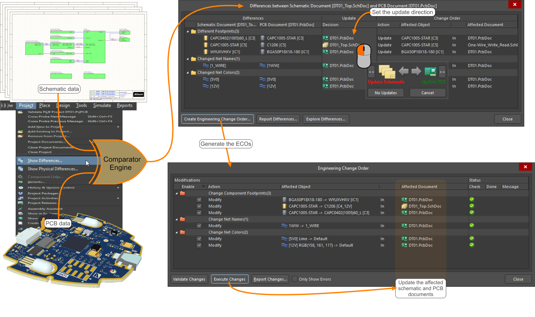 The synchronization process detects and resolves the schematic and PCB differences.
Design synchronization is performed directly between the schematic and PCB editors; there is no intermediate, netlist-like document used. The software uses a comparator engine to compare all aspects of the design, detailing the output as a list of differences. The designer decides which side should change to resolve the differences, and a set of Engineering Change Orders (ECOs) is created. When these are applied, the two sides of the design are back in sync.
Approaches to Synchronizing
There are two approaches to performing a synchronization:
-
Single-direction synchronization – the more common approach, used to push all changes from the schematic to the PCB, or from the PCB back to the schematic. This done using the Design » Update PCB or the Design » Update Schematic commands from the respective editors (
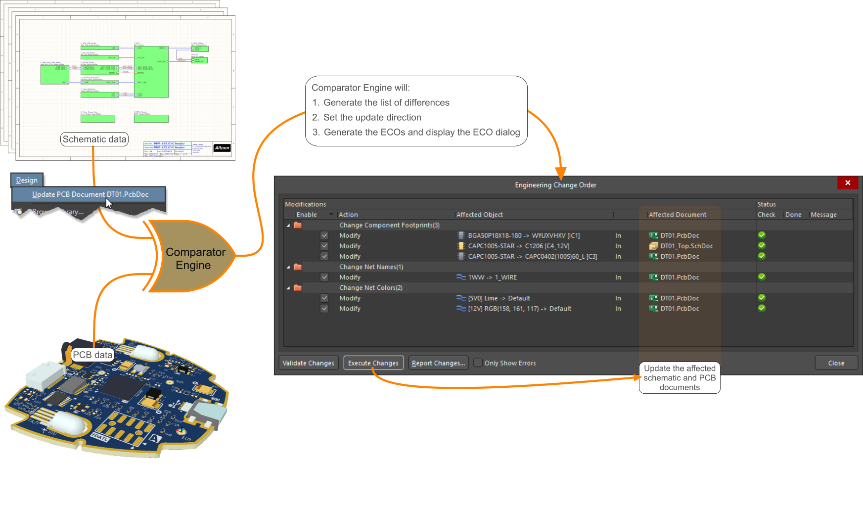 ). Refer to the Performing a Direct Update section to learn more about this approach.
-
Bi-directional synchronization – where differences can be updated in both directions simultaneously using the Project » Show Differences command, as shown in the image above. Bi-directional synchronization is typically only used in the specific situation where the design is being modified in both the schematic and PCB spaces at the same time. Refer to the Detecting the Difference Between Designs section to learn more about this approach.
What Can be Synchronized?
The synchronization process ensures that the component and connective data on the schematic, matches the component and connective data on the PCB. As well as the component and connective data, the synchronization process also ensures that other design constraints; such as net classes, component classes and design rules, are also in sync.
Configuring the Comparator Options
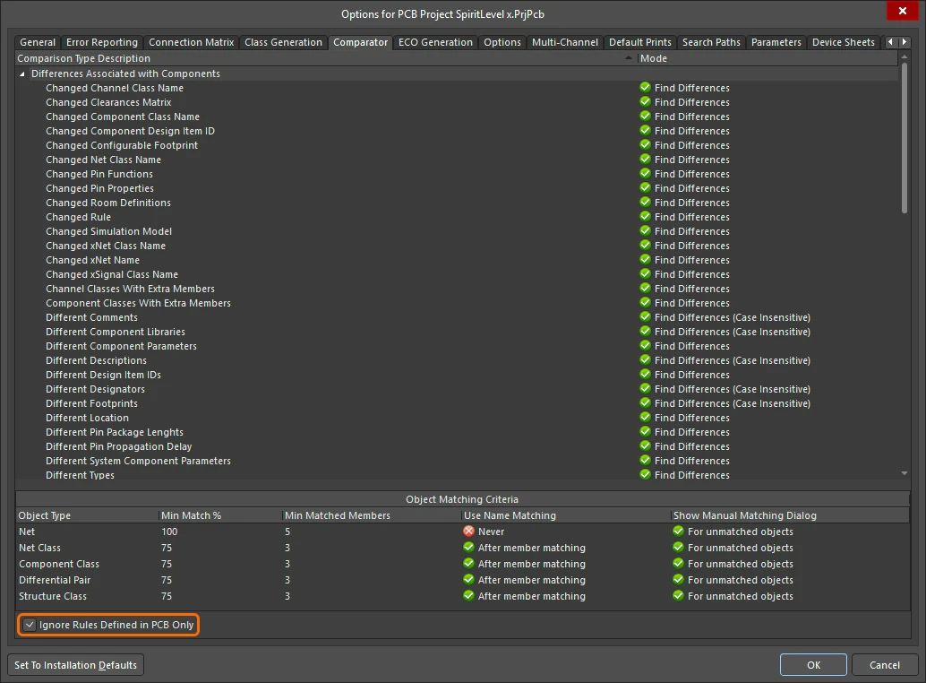
The first stage of the synchronization process is to compare the schematic to the PCB. Exactly what schematic and PCB data gets compared is configured in the Comparator tab of the Options for PCB Project dialog. Select Project » Project Options to open the dialog.

The comparator engine obeys the settings defined in the Comparator tab of the Options for PCB Project dialog.
Configuring the Comparator
| Types of comparison | The main region of the dialog displays a list of Comparison Types, such as Different Designators and Changed Net Name, grouped in 5 categories. |
| What to do | The Mode column on the right includes a dropdown for each, where you select the mode of comparison, such as Find Differences or Ignore Differences. Text-type comparisons have a third option, to allow the comparison to be case-insensitive. |
| Object Matching Criteria | Across the bottom of the dialog there are options for setting the Object Matching Criteria. Matching is a sophisticated, multi-pass process that does not rely on simple exact string matching. To learn more, refer to the Matching the Nets and Classes section of this page. |
| Ignore Rules Defined in the PCB Only | Enable this option to exclude the rules you have defined in the PCB from the comparison process. |
| Default behavior | The default for a new project is to Find Differences for every comparison type, set the options as required for your project. |
| Schematic to PCB synchronization | For schematic to PCB synchronization, all of the PCB related details can be synchronized. |
| PCB to schematic synchronization | For PCB to schematic synchronization, only changes made to the component designator, comment and footprint can be synchronized back to the schematic. The only net changes that can be synchronized are changes due to a pin or part swap operation - how this is carried out depends on how the pin/part swap options are configured. To learn more, refer to the Pin and Part Swapping page. |
Learn more about the Comparator tab of the Options for PCB Project dialog.
Synchronizing Net and Component Classes
As well as component and connective data, you can also generate and synchronize classes when you perform a Design » Update PCB. Classes are a logical collection of a particular type of design object. For example, a group of related components could be grouped into their own Component Class, which could then be used as the basis for creating a targeted rule. Use this tab to configure the generation of both automatically generated classes and user-defined classes, when the source schematic documents are synchronized with the PCB design document.
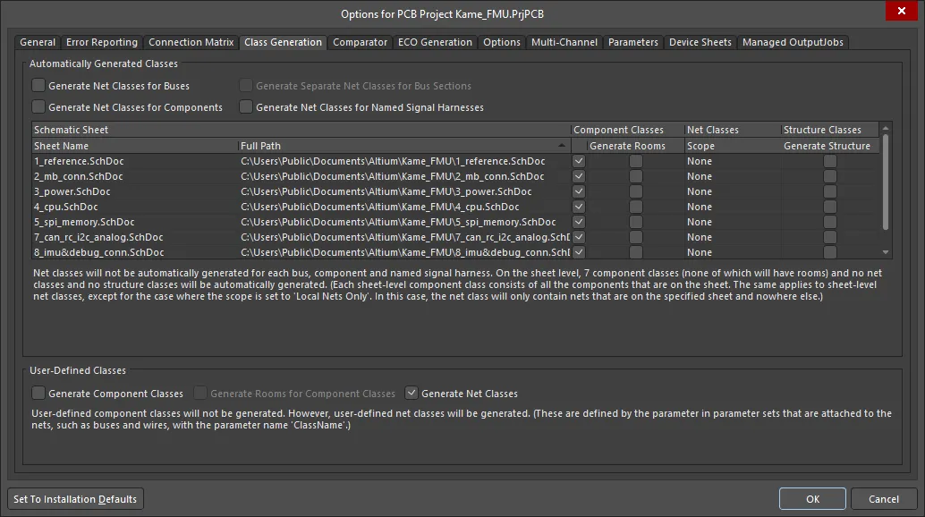 The Class Generation tab of the Options for PCB Project dialog.
Learn more about setting up the Class Generation tab.
Learn more about the generation and synchronization of classes from the schematic.
Synchronizing Design Rules
For a project using design rules (rather than the Constraint Manager), rules can be defined on the schematic by adding it as a special type of parameter. For schematic objects that include parameters, such as components, the rule is added in the Parameters section of the Properties panel. Otherwise, the rule is defined by placing a Directive, such as a Parameter Set or Differential Pair, so that it touches the object the rule is to apply to.
In the image below, a width constraint design rule that targets specific nets is being defined on the schematic, by defining the rule within a Parameter Set object. Rather than placing a Parameter Set object on each wire that needs a rule, a Blanket directive has been placed so that it covers both the net identifiers D- and D+, and then the Parameter Set object placed so that it touches the Blanket. The software knows that the requirements defined in the Parameter Set must be applied to all nets detected under the Blanket. As well as the width constraint, the Parameter Set also specifies that all nets detected under the Blanket are to be made members of the USB_data Net Class. This results in a single Width Constraint design rule being created in the PCB editor, scoped to target the USB_data Net Class.

The Parameter Set is used to define a net class and a design rule, to the nets under the schematic blanket object. Note that the required measurement units are configured at the bottom of the Edit PCB Rule dialog.
Synchronizing Design Rules
| How rules are defined on the schematic | For a project using design rules (rather than the Constraint Manager), rules can be added to the schematic by adding it as a special type of parameter. For schematic objects that include parameters, such as a component, the rule is added as a parameter. Otherwise, it must be added by placing a Parameter Setor Differential Pair Directive object so that it touches the object that the rule is to apply to. |
| Enable the transfer of rules | In the Comparator tab of the Options for Project dialog, ensure that the required Rule type comparisons are enabled, to allow design rules to be added and updated in the PCB. |
| Identifying schematic-based rules | Each PCB rule that is created from a schematic rule definition is automatically named Schematic <RuleType>. If required, this name can be edited as it is not used for ongoing rule synchronization. |
| Priority of schematic-based rules | Schematic-based rules are given the highest priority when they are added to the PCB design rules. Ensure that their priority is set to an appropriate level after design synchronization. |
| Creating a Class of objects and applying the rule to that class | Classes allow a design requirement to be applied to a set of objects, which means you can then define a single rule that applies to all members of that class. In the image above, the design rule is defined in a Parameter Set object that is attached to a Blanket. By including a Class definition in the Parameter Set object the PCB net class |
| Defining differential pairs and applying rules | Differential pairs can be defined and configured on the schematic, by placing Differential Pair directives ( |
 ).
Learn more about defining a design rule in the schematic.
Learn more about configuring differential pairs on the schematic.
Configuring the ECO Generation Options
The Options for Project dialog also includes an ECO Generation tab. This tab defines which design modifications can have ECOs created. Typically these are all enabled, with the options in the Comparator tab of the dialog being used to configure which design changes are to be synchronized between the schematic and the PCB.

The ECO Generation tab defines which types of modifications can have ECOs created.
Performing a Direct Update
Since the designer usually knows which way they want to apply the updates and those updates are all in the same direction, the most common approach to synchronizing is to perform a direct update. To do this you choose the Update command from the Design menu, from either the schematic editor or the PCB editor. Your choice of editor from which you run the command indicates the direction you want the changes to be made - from this editor, to that editor. For example, you would choose Design » Update in the schematic editor to push all changes from the schematic to the PCB.
The active PCB design document can also be with any changes that have been made to the source schematic documents by choosing the Design » Import Changes from <ProjectName> command, from the main menus of the PCB editor. Using this approach, the Differences between dialog is skipped and you jump straight to the Engineering Change Order dialog.
If all of the updates are going to be applied in the same direction, use the Design » Update command.
Resolving Differences - Applying the ECOs
Each difference is resolved by applying an Engineering Change Order (ECO). The modifications required in the ECO are listed in the Engineering Change Order dialog with one modification per line, each with its own Enable checkbox. The dialog has two main sections – Modifications that details each action, the objects it applies to, and the documented impacted by that change; and Status, which details if the action could be and has been applied.

Each design change presents as an ECO, enable those that are required.
Working in the Engineering Change Order Dialog
Working in the dialog |
|
| Enable required changes | The dialog opens with all changes enabled, disable any changes you wish to hold off for now. The dialog supports multi-select - use the right-click context menu to toggle the enable state of selected ECOs. |
| Validate before Executing | Use the Validate Changes button to check that the changes can be performed. ECOs typically fail because an object is not available - for example, the specified PCB footprint does not exist in the Available File-based Libraries, or the specified pad does not exist on the footprint. |
| If an ECO fails | An ECO can also fail because an object that is needed by that ECO was not present, but is due to be added during the processing of the current ECOs. In this situation, run the Update command a second time to complete that ECO. |
| Explore the design | Use the right-click Cross Probe command to examine the objects affected by an ECO. |
| When expected modifications are not listed in the ECO dialog | If the Mode for a modification type has been set to Ignore Differences on the ECO Generation tab of the Project Options dialog, any design update that results in the action of this modification type are not transferred to the Engineering Change Order dialog. |
Modifications Section |
|
| Enable | This option determines whether or not the modification will be included when the ECO is executed.
|
| Action | The specific action to be carried out. The types of actions are dependent on what type of ECO needs to be done. |
| Affected Object | The object affected by the action. |
| Affected Document | The document upon which the action will be carried out. |
| Right-click menu | Right-click in the dialog to:
|
Status section |
|
| Check | This field shows the result of running a validation check on the modification. A green check ( ) means that the proposed change is supported and will be carried out upon execution of the ECO. A red cross (  ) means that the proposed change is invalid and will not be carried out when the ECO is executed. |
| Done | This field shows the result of the execution of the modification. A green check () means that the valid modification executed successfully. |
| Message | If the modification fails the validation stage, an entry will appear in this field (and also in the Messages panel), giving an indication as to why it failed. |
Additional Dialog Controls |
|
| Validate Changes | Click to run a validation check on the modifications enabled for inclusion in the ECO. Validation results will appear in the Check column in the Status region of the dialog. |
| Execute Changes | Click to execute the ECO and effect the valid changes contained therein. Execution results will appear in the Done column in the Status region of the dialog. Remember that only changes that pass the validation stage will be executed. |
| Report Changes | Click to generate a report for the modifications contained in the ECO. The report will be loaded into the Report Preview dialog, listing all modification entries regardless of whether they validate and execute successfully. |
| Only Show Errors | check this option to only show Engineering Change Order errors. Validated changes will not be displayed. Showing only the list of errors will enable you to quickly review and make necessary changes to your design so that the resulting ECO validates completely. |
Detecting the Difference Between Designs
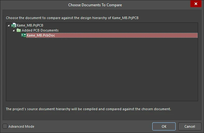
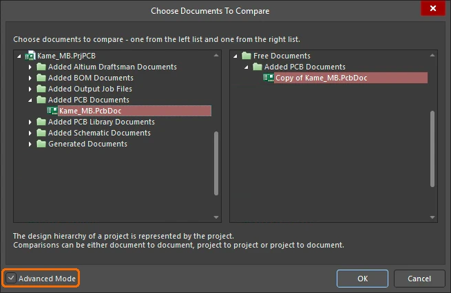
Altium Designer can compare any two designs and detail the differences between them. The Choose Documents to Compare dialog is used to select what two documents/document-sets to compare, for example the schematic project against the PCB. You can also use this dialog to compare any document to any document by ticking the Advanced Mode option.
Support for detecting differences includes:
-
Show Differences – a logical comparison of one design against another, for example a schematic design against the PCB, or a netlist against the PCB.
-
Show Physical Differences – used to perform a physical (graphical) comparison of one schematic or PCB document, against another.
Both the Project » Show Differences and Project » Show Physical Differences commands open Choose Documents to Compare dialog, as shown below.
Options and Controls of the Choose Documents to Compare Dialog
| Basic mode | In the default Basic mode, the entire schematic project is compared against the document selected in the document tree, as shown in the first slide above. |
| Advanced Mode | In Advanced mode, the document selected on the left is compared against the document selected on the right, as shown in the second slide. This is the mode you would use to compare a netlist to the board, a board to a board, or a schematic sheet to another schematic sheet. |
| Clicking OK | The outcome when you click the OK button depends on which command was used to open the Choose Documents to Compare dialog:
|
Exploring Design Differences
The design synchronization feature is able to detect and resolve differences in both directions; that is, from the schematic to the PCB, or from the PCB back to the schematic. When the comparator engine compares the schematic project to the PCB, a complete list of differences is created - at this stage there is no assumption on which side must be changed to bring them back into sync.
The software is capable of resolving these differences by applying changes to both sides, at the same time. For example, imagine the scenario where the electronics designer has changed the value of a capacitor, while the PCB designer has changed the footprint of that same capacitor. These two differences can be resolved in a single update process, by applying the comment change as a schematic-to-PCB update, and the footprint change as a PCB-to-schematic update (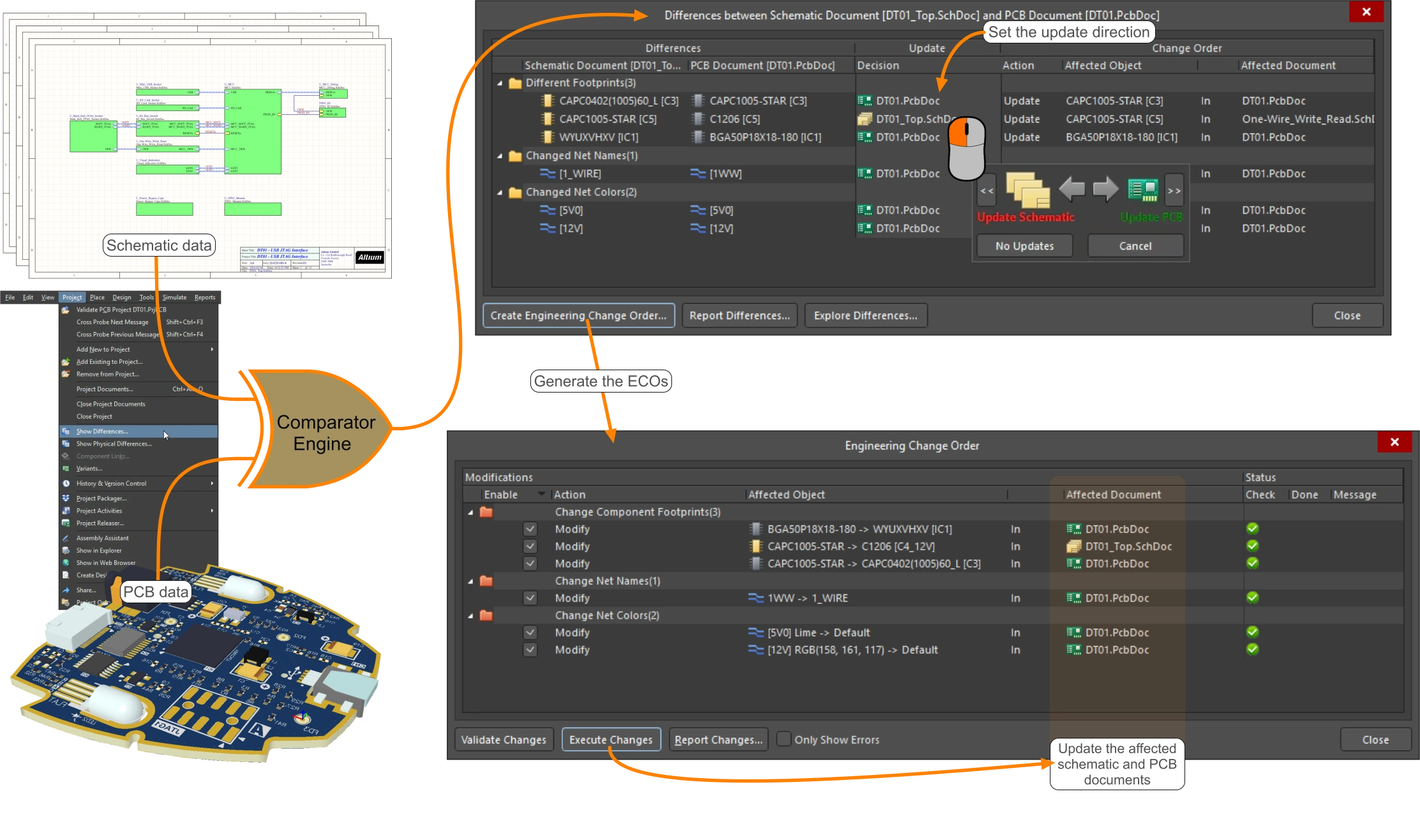 ).
The list of differences can be seen in the Differences between dialog.

Options and Controls of the Differences between Dialog
| Differences section | List of all of differences that the Comparator has found between the chosen documents, in a separate column for each document.
|
| Update section | The central region of the dialog is used to specify which document should be updated in order to resolve the difference. By default, all Decision entries initially have a decision of No Change applied to them. Assign an update direction to each difference:
|
| Change Order | For each difference that you decide to act on, this region of the dialog lists – the action to be taken, the object affected by the action, and the document upon which the action will be carried out. It is this information that is used to compile the subsequent ECO that will be used to create the updates. Common actions that will be listed in this area are:
|
| Right-click Menu | Right-click in the dialog to:
|
| Create Engineering Change Order | Click to generate the ECO. The Engineering Change Order dialog will appear from where you can validate and execute the updates in order to synchronize the documents. Learn more about applying the ECOs. |
| Report Differences | Click to generate a report for the differences found by the Comparator. The update decisions you have decided to make and the actions will be included in the generated ECO. The report will be loaded into the Report Preview dialog. Use this dialog to browse the report before ultimately exporting it to one of various supported formats or printing it directly. |
| Explore Differences | Click to investigate further the differences found by the Comparator prior to generating an ECO. The Differences between dialog will close and you will be returned to the main workspace with the Differences panel open. The panel will contain all of the differences listed by the Comparator and in the same categories. Use the panel to cross probe to an object responsible for a difference on its parent document. |
 )
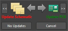 ).
The Differences Panel
The Differences panel is used to display the logical or physical differences found by the software's built-in Differences Comparator when comparing design documents (for example, when comparing the source document hierarchy (schematics) for a project against the PCB design document). The panel allows you to interactively explore the differences before the decision to create an Engineering Change Order (ECO) that will be used to synchronize the project documents.
Click on an entry in the results to cross probe to that object in the design.
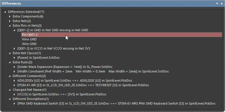
The Differences panel displays a hierarchical view of document differences.
Working in the Differences Panel
| Panel Access | To open the Differences panel:
|
| What differences are detected and displayed |
|
| Working in the panel |
|
 ).
Understanding the Linking Between the Schematic and the PCB
Rather than relying on the designators to link the schematic and PCB components, Altium Designer uses unique identifiers.
Component Matching via Unique Identifiers
Each schematic component links to its PCB component through a Unique Identifier (UID). The UID is automatically assigned when the schematic component is placed on the sheet. When component information is transferred for the first time between source schematic documents and the blank PCB using the Design » Update PCB command, each PCB component is automatically assigned the UID from the matching schematic component.
While this scheme would be adequate for a simple design, it is not capable of supporting a multi-channel design. In a multi-channel design, the same schematic component is repeated in each physical channel, which would mean the repeated PCB components would have the same UID. To cater for this, the UID for the PCB component is actually created by combining the UID of the parent Sheet Symbol with the UID of the schematic component. The syntax of the PCB UID changes slightly, depending on how the multi-channel design has been created.
For a multi-channel design created by placing multiple Sheet Symbols that all reference the same schematic sheet, each Sheet Symbol can provide a unique ID so the PCB UID has the format:
\SheetSymbolUID\SchComponentUID
For a multi-channel design created using the Repeat keyword, there is only 1 Sheet Symbol UID available, so the PCB UID also includes the ChannelIndex value, in the format:
\ChannelIndex+SheetSymbolUID\SchComponentUID
When the Components are not Linked
The advantage of using a UID to match the schematic and PCB components is that it allows the designators to become unsynchronized (perhaps by performing a PCB re-annotate a number of times), without any risk of the schematic and PCB becoming unsynchronized.
During design synchronization, if there is a component present on the schematic or the PCB that does not have a matching component (same UID) present in the other editor, the following will occur:
-
If the extra component is only present in the source editor, an ECO is created to add the component to the target editor.
-
If the extra component is only present in the target editor, an ECO is created to remove the extra component.
-
When there are unmatched components present in both editors the software needs instruction on how to deal with them, so the Failed to Match Unique Identifiers dialog opens.
 The Failed to Match Unique Identifiers dialog.
Options and Controls of the Failed to Match Unique Identifiers dialog
| Automatically Create Component Links | Click this button if you know that the unmatched components already have matching designators. Using the component designators, the software will assign matching UIDs to these extra components. For components that can be matched by designator, any other property differences (such as unmatched parameters), will result in ECOs being generated. If there are components that cannot be matched by designator, ECOs to add/remove these will be generated (extra components present in the source editor to be added, extra components in the target editor to be removed). |
| Manual Component Links | Click this button if you know there are components that match, but do not know the status of their designators. The Edit Component Links dialog will open (described below), where you can manually select each source and target component and transfer them to the matched components list, assigning them matching UIDs. ECOs will then be generated to synchronize the designators (and any other unmatched component properties). |
| Cancel | Click this button to generate ECOs to add extra components that are present in the source editor and remove extra components from the target editor. |
Manually Linking Components
The status of the component links between schematic components and their corresponding PCB component footprints can be checked and managed at any time, in the Edit Component Links dialog (PCB editor, Projects » Component Links command). Components that are unmatched are presented in the two Un-Matched Components columns on the left, components that share a matching UID are presented in the Matched Components region on the right of the dialog.

The Edit Component Links dialog is used to detect and resolve UID mismatches, it must be run from the PCB editor.
Options and Controls of the Edit Component Links dialog
| Un-Matched Components | Schematic and PCB components that are unmatched are presented in the relevant Un-Matched Components column on the left. A component being listed in either of these columns indicates that a component with the same UID does not exist on the other side. |
| Matched Components | A list of components that share a matching UID are presented in the Matched Components region on the right of the dialog. |
| Add Pairs Matched By | Click to scan the list of currently unmatched components and attempt to match them by the enabled properties (Designator, and Comment, and Footprint). |
| Perform Update | When this button is clicked, each newly matched PCB component is assigned the UID of its schematic counterpart. If you have moved any entries in the Matched section of the dialog back into the Unmatched sections, a confirmation dialog will appear advising that existing component associations will be broken by proceeding. Clicking Yes will proceed with the update and an information dialog will appear giving a summary of the component links modified in the PCB document. A new entry in the Matched section is summarized as a Link Modified, whilst a previously linked entry that you have now unmatched is summarized as a Link Removed. |
| Manually matching components | To manually match a schematic component to a PCB component, select the schematic component in the first Un-Matched Components column, select the PCB component in the second Un-Matched Components column, then click the right-arrow button ( ). |
| Double-click behavior | Double-click can be used to match the currently selected schematic component (in the first Un-Matched Components column) with the currently selected PCB component (in the second Un-Matched Components column). Be careful using this approach, it is based purely on what is currently selected. |
| |
Click to match the currently selected unmatched schematic component (first Un-Matched Components column) to the currently selected PCB component (second Un-Matched Components column). These components are removed from their respective unmatched lists, and added to the Matched Components list. |
 |
Click to unmatch the component currently selected in the Matched Components list. The component is removed from this list and added to the respective Un-Matched Components lists. |
 |
Click to unmatch all of the component in the Matched Components list. All components are removed from this list and added to the respective Un-Matched Components lists. |
Matching the Nets and Classes
Both nets and classes have a parent (the net or class), and children (the members of that net or class). Matching these requires a different approach than the UID mechanism used for component linking, to support changes to: the parent; the children; or both the parent and its children. For example, something as simple as changing the name of a net on the schematic should not require that net and all its children pins be removed from the PCB, then the newly named net be added, and finally all the children pins be added to that new net.
To support this, the software includes separate matching algorithms to match nets and classes by their members, and also by their name. The matching process is configured in the Object Matching Criteria section of the Comparator tab of the Options for Project dialog.

The default settings is to match members first, then by Object Type name.
Matching for these types of objects is handled in the following way:
-
During design synchronization, the default behavior is to first attempt to match by members (configured in the Use Name Matching column), in accordance with the Min Match % and Min Match Member settings.
-
If member matching fails, the software will then attempt to match by name (if the Use Name Matching option is not set to
Never). -
If either of these matching processes succeeds, you will proceed to the Engineering Change Order dialog.
-
If both matching techniques fail (or the Use Name Matching option is set to
Never), the Match Manually dialog will open ( ).
-
Clicking No in the Match Manually dialog will skip the user-matching process and jump straight to the Engineering Change Order dialog. Since you have not attempted to match any unmatched objects, the software assumes that the reference and target objects are unrelated, so ECOs will be generated that remove the Unmatched Reference Objects from the board, and add the Unmatched Target Objects as new objects.
-
If you click Yes in the dialog to match manually, the Match dialog will open, as shown below (the dialog caption changes to suit the unmatched object type).
 The Match dialog is used to manually match objects that you know to be matched. Leave the right side empty and click Continue if you are unsure.
Options and Controls of the Match Dialog
| Unmatched <Object> |
|
| Matched Pairs | Lists matched Reference Object and Target Object pairs that have been defined. |
| Continue | Click to accept the matching updates and open the Engineering Change Order dialog. For the objects listed in the Matched Pairs column the software generates an ECO to update the names so they now match, and ECOs to remove/add members, so they also match. |
| Manually matching | Select an object in the Unmatched Reference Objects list, select the object that it matches in the Unmatched Target Objects list, then click the right-arrow button ( |
 |
Click to match the selected reference and target objects and move the selected object(s) from the Unmatched region to the Matched Pairs region. |
 |
Click to move the selected object(s) from the Matched Pairs region to the Unmatched region. This action will cause the moved objects to be unmatched. |
 |
Click to move all objects from the Matched Pairs region to the Unmatched region. This action will cause the moved objects to be unmatched. |
Matching the Design Rules
Design rules that are defined on the schematic are linked to the matching rule on the PCB. UIDs are used to link the schematic design rule to the PCB design rule, allowing you to update the rule on the schematic and flow those changes to the PCB, and to rename the rule in the PCB editor. The UID is automatically assigned in the schematic editor, and transferred to the PCB during design design synchronization.
 Design rules use a UID to match the schematic design rule definition to the PCB design rule.
-
Typically, you will not need to manually manage the matching of rules, unless you have manually edited the UID in the PCB Rules and Constraints dialog in the PCB editor.
-
If the UIDs do not match, the software will add a new rule to the PCB for any schematic rule that does not have a matching PCB rule, and remove any PCB design rule that does not have a matching schematic design rule.
-
If you do not want to remove rules defined in the PCB editor that have not been defined in the schematic, enable the Ignore Rules Defined in the PCB Only option in the Comparator tab of the Options for Project dialog (
 ).