Draftsman Enhancements
This document is no longer available beyond version 17.1. Information can now be found here: Streamlining Board Design Documentation with Draftsman for version 24
The Altium Designer 17.1 release brings a range of new features and enhancements to the Draftsman production drawing application. The updates include a new Isometric View, Surface Finish indicators, View Title positioning, the ability to split a BOM over several tables, plus more. The release also incorporates a range of Bug Fixes and drawing feature enhancements.
Isometric View
Adding to the range of automated board production drawings that can be included in a Draftsman document, an Isometric View is now available for placement, along with the other main Assembly and Fabrication views.
An Isometric Projection view for the currently specified PCB is placed in a document with the Place » Board Isometric View command. The properties and options for a placed Isometric View can be edited from the Draftsman Properties panel, which will change to its Board Isometric View mode when the view graphic is selected in the workspace. Use the panel's View – Face Side drop down menu to select the projection view perspective.
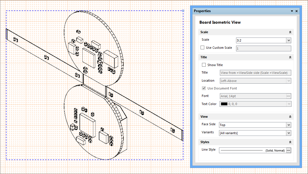
If the Properties panel is not already open, it can be activated by double-clicking on a placed drawing view, by selecting the drawing view and choosing Properties from the right-click option menu, or by clicking on the  button at the bottom of the work area.
Split BOM tables
The Bill of Materials (BOM) document for most advanced PCB projects tends to have a large number of entries, which can be difficult to recreate as a table that will fit into a drawing document. Rather than resorting to font and table scaling, multiple custom table entries or an external document, the Split BOM capability in the Properties panel allows the Draftsman BOM Table to be presented over a number of Pages.
To create the multiple BOM Pages, select a placed BOM (which is likely to exceed the document Sheet height) and check the Limit Page Height box in the Properties panel’s Pages section. This will restrict the height of the BOM table to the nominated height entry (Max Page Height, mm), and therefore the number of lines shown in the BOM table.
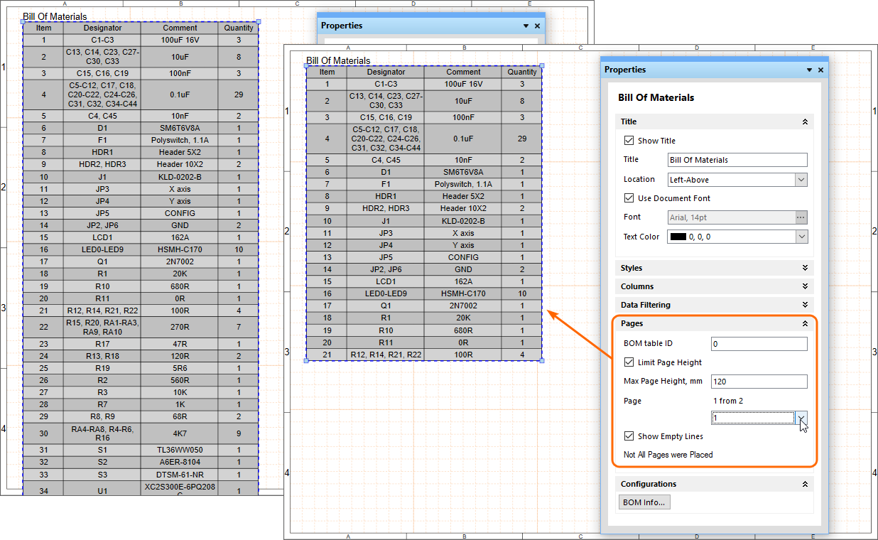
Draftsman detects that the entire BOM is not shown, as indicated by the panel's Page entry (for example, 1 from 2), and the associated drop down menu allows you to nominate which Page is shown. To add further Pages of the BOM, place another BOM (Place » Bill of Materials) and specify the next page under Page in the Pages section of the Properties panel.
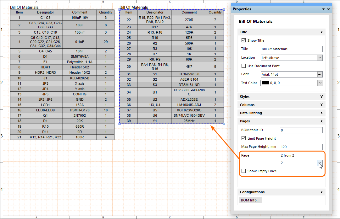
Since each Page of the BOM is placed by adding another BOM table, and then configuring it accordingly, the individual BOM Pages (sections) can be placed on any Sheet in a Draftsman document. To place another, different set of split BOM Pages, specify an alternative BOM Table ID on a placed BOM – say, 1 rather than 0.
Design Variants and OutJobs
Altium Designer's ability to create variations of a board design (Variants) means that the variant information is also passed on to Draftsman, which in turn allows a design variation to be applied to a placed drawing View.
Specifying Variants in Output Jobs
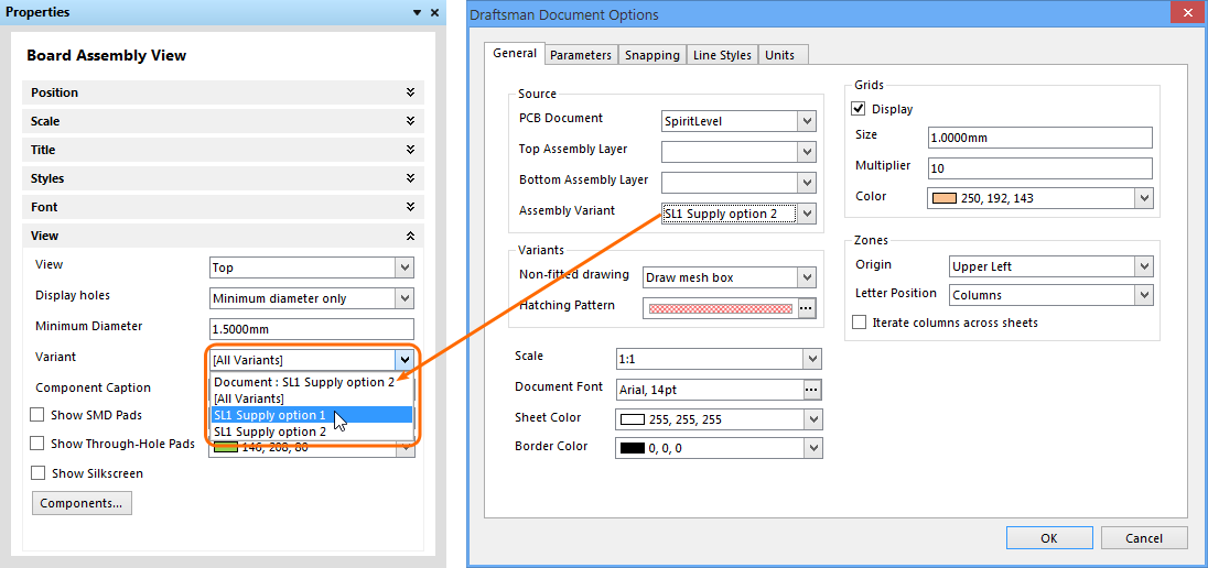
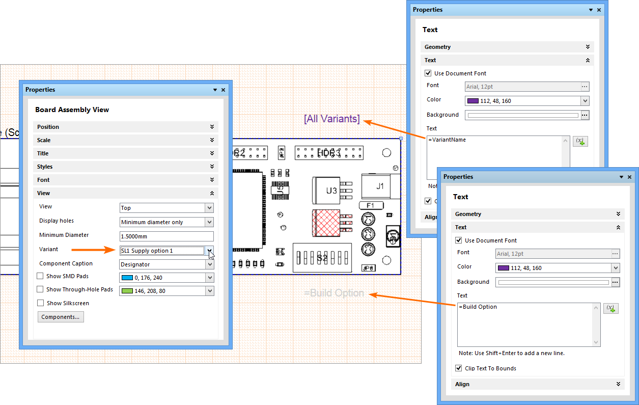
The Variant that applies to a selected drawing view, such as a Board Assembly View, is nominated from the Variant drop down menu in the Properties panel. This offers the choice of Variants defined in the project's Variant Management dialog, and includes the option of selecting an Assembly Variant that has been specified at the Draftsman document level – via the Draftsman Document Options dialog.
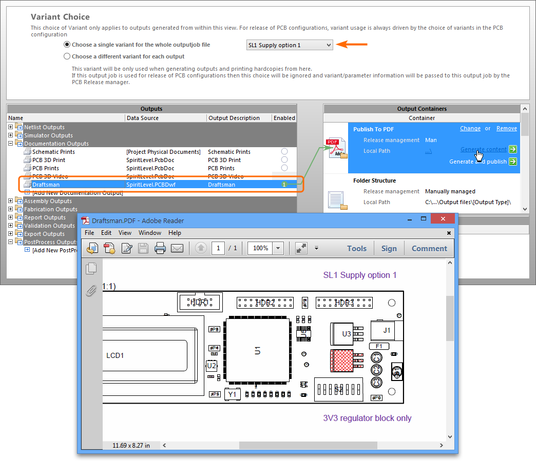
In turn, the Variant option that has been selected in the Properties panel will affect how variants are handled in a project Output Job:
- Document level Variant – if a document defined variant option (
Document:[xxx]) is selected for the Draftsman drawing view object, the Variant that is applied in an Output Job is determined by the OutJob’s Variant choice settings.
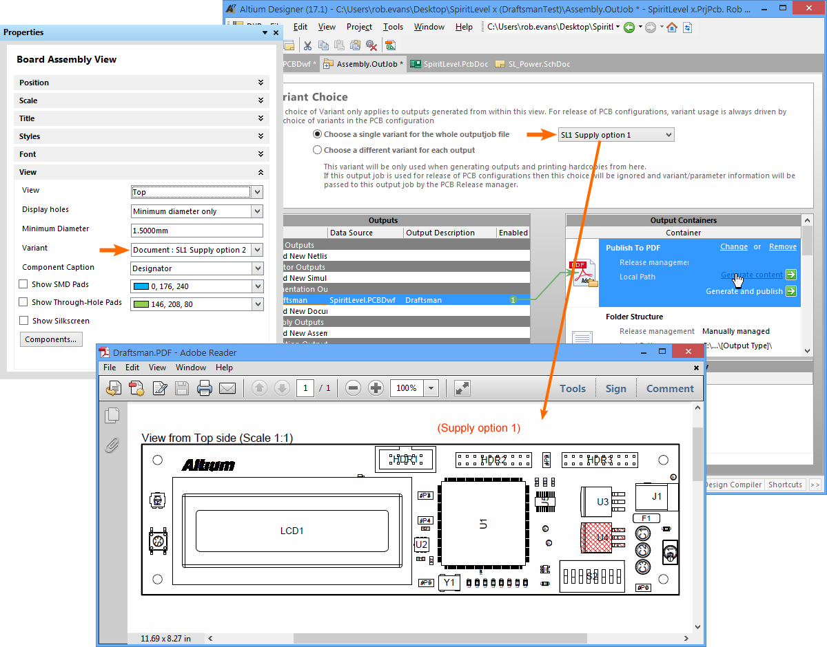
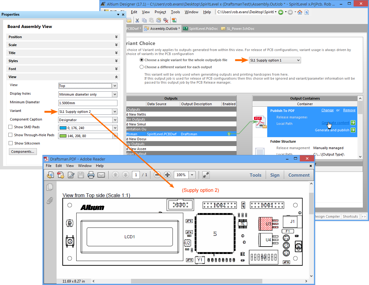
- Drawing View Variant – if a standard Variant option (
[variant]) is selected for the drawing view object, the Variant that is applied in an Output Job is determined by the Drawing View’s Variant choice – the Variant selected in the Output Job does not apply.
Variant Parameters in OutJobs
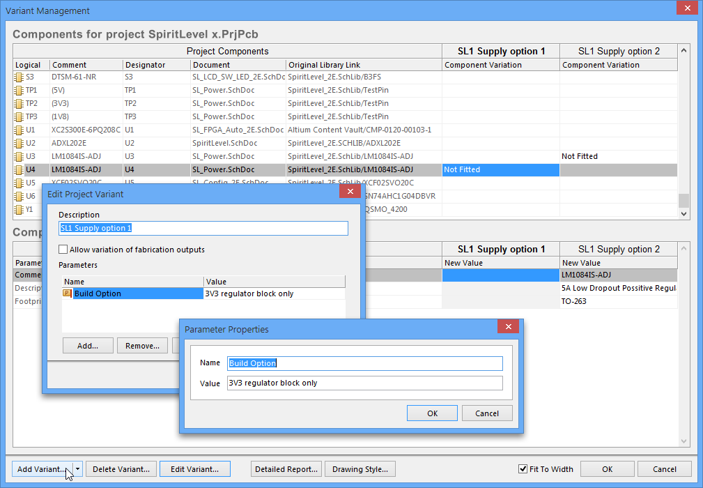
Project Variants are added in the project's Variant Management dialog, which also allows Parameters to be added to each variant. These parameters are typically applied as special (interpreted) strings in Altium Designer documents to indicate which Variant is currently enabled.
In Draftsman, a project’s current variant selection is made from the Variant menu in the in the View region of the Properties panel, which causes the placed view (such as an Assembly View) to change to reflect the variation, and apply mesh rendering where required – see Tools » Document Options for the Variant rendering settings.
Special strings, such as the VariantName and Variant Parameters can be placed in the drawing as free strings, or for a more universal solution, included in the title block of Draftsman sheet templates – see the Document Parameters dialog for a list of the available parameter strings.
When a saved Draftsman document is subsequently generated from an Altium Designer Output Job, the parameter special strings are interpreted in line with the Variant selected in the OutJob.
Surface Finish Indicators
Draftsman now allows the placement of Surface Finish graphical symbols and their associated parameters that comply with the ISO 1302:2002 International Standard for surface texture in technical product documentation. The standard specifies the rules for the indication of surface texture in drawings, based on special symbols and attributes that describe the permitted surface material for the product – in this case, a printed circuit board.
The addition of Surface Finish indicators in Draftsman avoids the need for a separate Surface Finish tool or application when this standardized information is required for PCB manufacture. The graphical symbols are accompanied by a range specialized text codes, as defined by the ISO standard, that are added via the Draftsman Properties panel when a placed Surface Material object is selected.
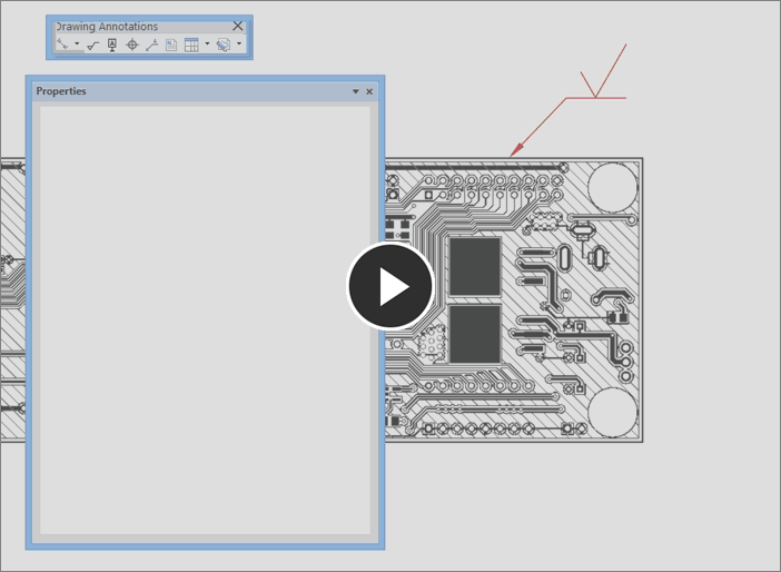
To place a Surface Material symbol in a drawing, select Place » Surface Finish from the main menu, and then locate the symbol where it is associated with the board surface. Attach the symbol to a drawing by clicking on a highlighted line and then clicking again to place the symbol. The attached surface indicator can be dragged along the line, and optionally, away from the drawing via an automatic Extension Line. Select the With Leader option in the Properties panel to freely position the symbol.
In most cases only one or two surfaces need to be defined, such as the surface of the top and bottom layers, so a minimal number of symbols/attributes are usually required.
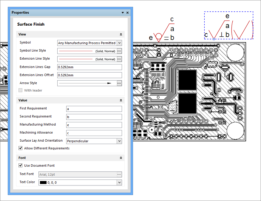
The style of the Surface Finish symbol itself indicates the allowed processing of the surface material, as follows:
-
 Any manufacturing process permitted (default).
 -
 Material shall be removed.
 -
 Material shall not be removed.
 - A symbol enclosed in brackets is appended to the indicator when the panel's Allow Different Requirements option is checked.
The string-based parameters (attributes) that are associated with the symbol indicate a range of manufacturing options, as defined by the standard.
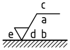
- First requirement (
a) - Second requirement (
b) - Manufacturing Method (
c) - Surface Lay and Orientations (
d)- Predefined options, with matching symbol graphics, as selected from the drop down menu in Draftsman's Properties panel (default is
None)
- Predefined options, with matching symbol graphics, as selected from the drop down menu in Draftsman's Properties panel (default is
- Machining Allowance (
e)
– See the ISO Geometrical Product Specifications page for more information about the ISO 1302:2002 standard.
Geometric Dimensioning and Tolerances
Draftsman now includes the capability to place and configure industry standard Geometric Dimensioning and Geometric Tolerances symbolic elements that define the manufacturing properties of objects included in a drawing.
Also used in most advanced MCAD applications, the specialized information provided by the placed geometric symbols stipulate the allowable imperfections in the manufacture of physical objects. The geometric definition elements that can be added to Draftsman documents are derived from standards developed by the American Society of Mechanical Engineers (ASME) – specifically, the ASME Y14.5-2009 Dimension and Tolerancing standard. Many other standards and guidelines exist for geometric engineering definitions, including a large number of conceptually specific documents from the International Organization for Standardization (ISO).
– See Geometric dimensioning and tolerancing for overview information and reference links.
In terms of Draftsman engineering documents, the symbol-based Dimensioning and Tolerancing information is incorporated into a drawing by the placement of two new types of objects:
- Datum Feature symbols – Identification objects that can be attached to a line, point or axis of a physical feature in a drawing, such as the edge of board, component or hole.
- Feature Control Frames – Information objects that can be attached to a drawing feature, which include multiples of symbolic data that specify the mechanical manufacturing constraints for the feature.
Both of the above drawing objects can be positioned freely in the document, or (normally) attached to a feature such as an edge. In the same way in which other Drawing Annotations are placed in Draftsman, such as Surface Finish symbols, the geometric definition symbols are attached by clicking on a highlighted line in the drawing and then clicking again to place the symbol.
Datum Feature
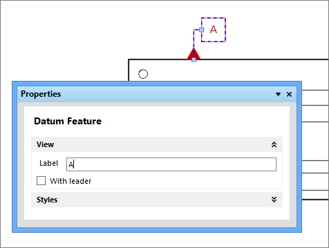
Place a Datum Feature on a drawing using the Place » Datum Feature menu command or by selecting the ![]() icon from the Drawing Annotation toolbar, and attach it to a drawing feature as outlined above. The attached Datum element simply identifies that feature, such as an edge, as a reference on that drawing object.
icon from the Drawing Annotation toolbar, and attach it to a drawing feature as outlined above. The attached Datum element simply identifies that feature, such as an edge, as a reference on that drawing object.
The Datum Feature is identified by its Label entry in the Properties panel, so that relative dimension tolerances included in Feature Control Frames (see below) can refer to this and other placed datum.
Feature Control Frame
Place a Feature Control Frame on a drawing using the Place » Feature Control Frame menu command or by selecting the ![]() icon from the Drawing Annotation toolbar, and attach it to a drawing feature as outlined above, or place it free space.
icon from the Drawing Annotation toolbar, and attach it to a drawing feature as outlined above, or place it free space.
The information it conveys, presented in symbols, modifiers and numeric values, is entered in the Properties panel.
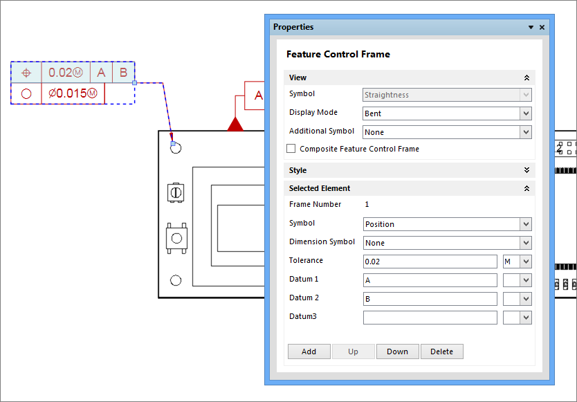
A Feature Control Frame offers symbol options and large number of elements that can be attached to specify manufacturing tolerances and constraints. Attached machining tolerances, such as the 'straightness' of a feature for example, apply to the specified drawing object face. Attached Dimension tolerances by comparison (such as 'position') are generally specified as relative to one or more placed Datum.
Applied Geometric Tolerances
When added to the mechanical elements in a Draftsman drawing view, the combined information represented by Feature Control Frames and their related Datum references can fully describe the acceptable manufacturing constraints for that physical element.
In the example drawing view shown below, dimensions have been added, Datum Feature references attached to the three visible board edges, and Feature Control Frames applied to the top edge and two mounting holes. The Feature Control Frames have multiple elements added, which appear as a sequence of (selectable) rows – note the Add, Delete etc buttons in the Selected Element area of the Properties panel.
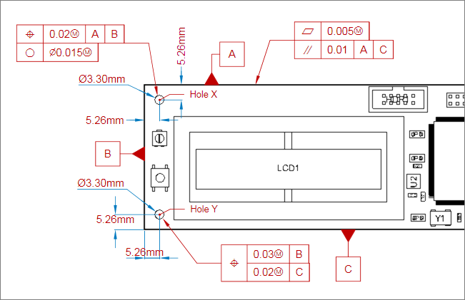
The symbols and formatting used in the various Feature Control Frames is fully described in the ASME standard, however an overview of the examples shown above is as follows:
- Frame attached to edge A
- First element (top row) – stipulates the flatness tolerance (acceptable deviation in the surface) for the board edge.
- Second element – stipulates parallel tolerance (acceptable distance, and therefore angle deviance) between sides A and C.
- Frame attached to Hole X
- First element (top row) – stipulates the hole position tolerance (acceptable positional error) relative to both Datum A and Datum B.
- Second element – stipulates the roundness tolerance (acceptable diameter variance) for the hole.
- Frame attached to Hole Y: A Composite Feature Control Frame (as selected by the related checkbox in the Properties panel)
- Symbol for this frame (first column) – defines this Frame as positional information, for all elements (rows).
- First sub element – stipulates the tolerance (acceptable error) for Hole Y relative to Datum B.
- Second sub element – stipulates the tolerance (acceptable error) for Hole Y relative to Datum C.
- Symbol for this frame (first column) – defines this Frame as positional information, for all elements (rows).
Manual Designator control
Further flexibility has been added to Draftsman with the inclusion of manual component Designator control and positioning. This adds to the capabilities available in the Component Display Properties dialog by providing direct control through the Properties panel of the positioning, sizing and style for individual designators, or designators on a BOM item basis. Also, designators may be manually positioned in the drawing space by a simple drag and drop process.
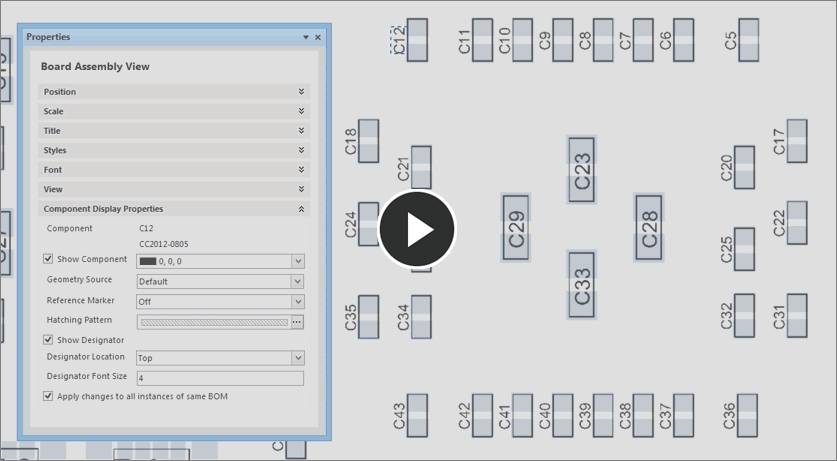
The immediate control of designators is accessed from a new Component Display Properties section in the Properties panel, which is enabled when a component or its designator is selected in a placed Assembly view. For the selected component, the designator properties are equivalent to those for its specific component entry in the Component Display Properties dialog – opened by selecting the  button in the panel’s View section.
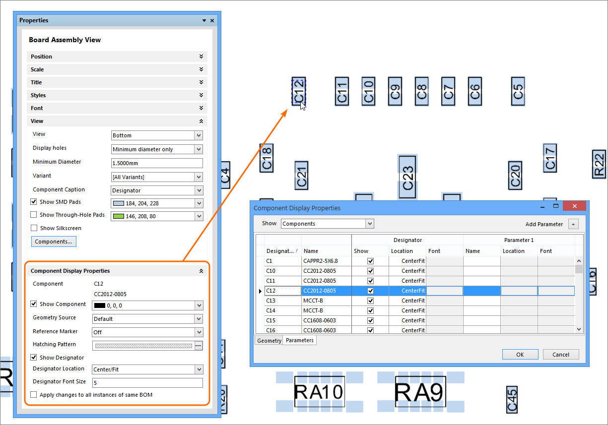
Changes made in the panel’s Component Display Properties will affect the currently selected component in the drawing view. To change the properties for all components of that type, check the Apply changes to all instances of same BOM option. This will detect the component’s BOM item entry and propagate the property change to all those components.
For example, to modify the display properties for all 0.1uF capacitors with the CC2012-0805 footprint (the BOM entry for a selected bypass capacitor), select the Apply changes to all instances of same BOM option and then make the component display property change. This is equivalent to locating and changing the properties of the BOM entry in the Component Display Properties dialog.
For direct free-form placement of a component dialog, simply press Ctrl while selecting the designator in the workspace and then drag it to a new location. Press the space bar to rotate the designator by 90° steps while you drag. Note that its Designator Location setting in the Properties panel will change to Manual.
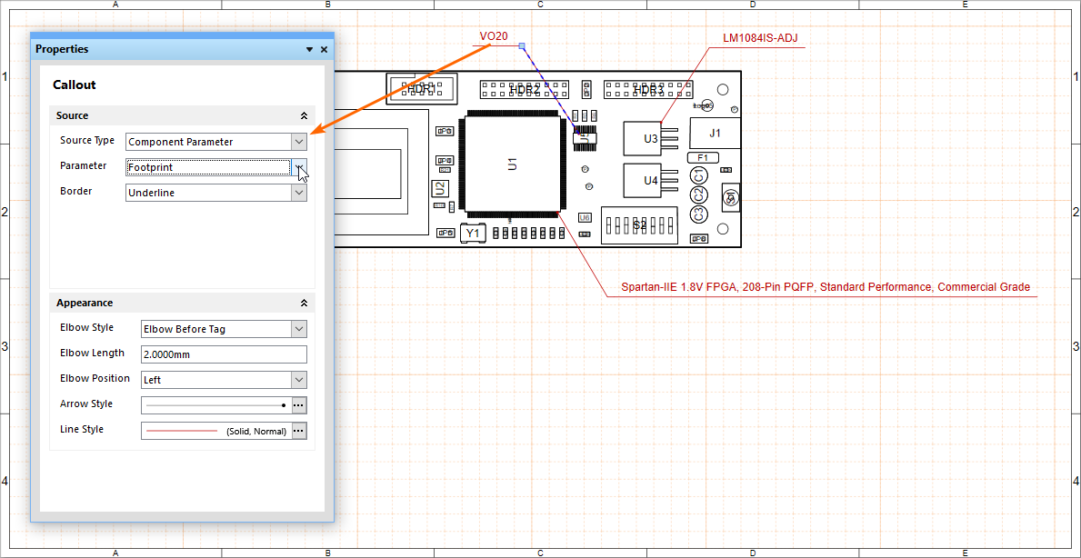
Component Parameters in Callouts
Adding further flexibility to Draftsman’s Callout feature, a new Component Parameter option is available as the Callout Source Type data.
When selected, the Component Parameter source can be set to specify one of the available parameters for the Component selected by the Callout, as extracted from the Assembly View PCB document. Use the Properties panel Parameter drop down menu to nominate the displayed Parameter data.
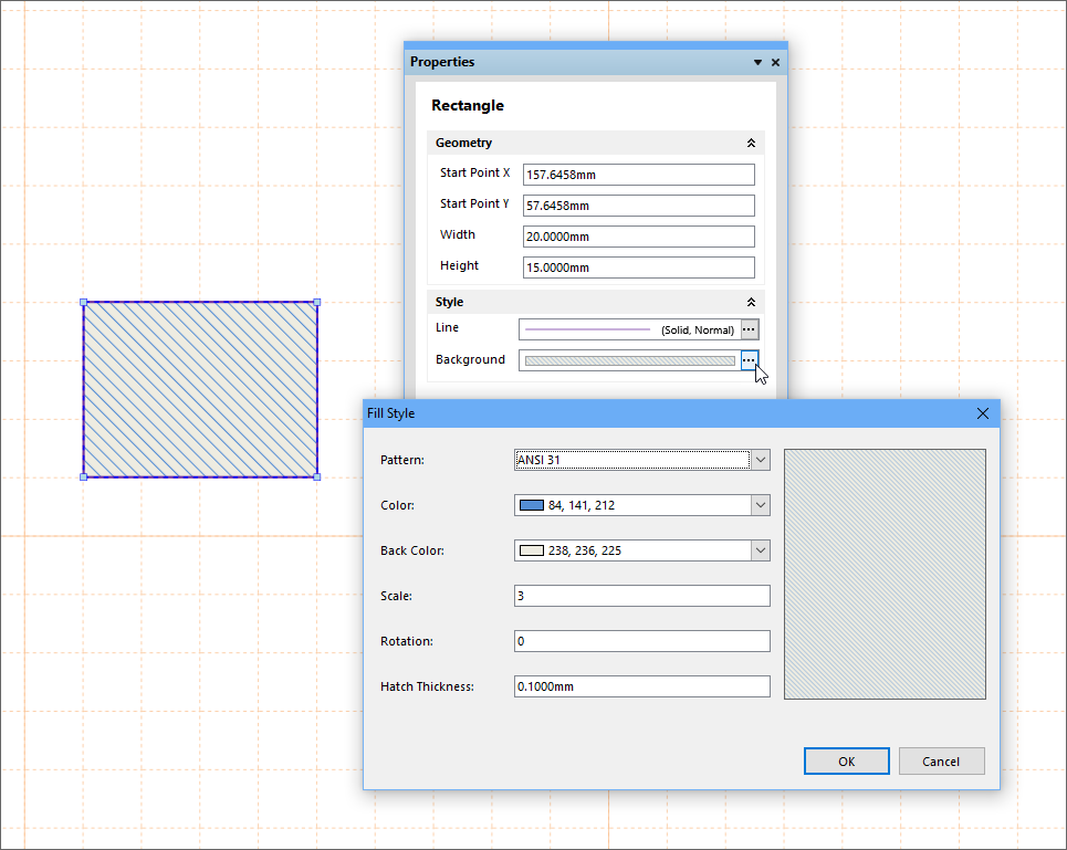
Drawing Shape Fill
The background style for primitive drawing objects such as Rectangles and Circles can now be set to solid or hatched ANSI-style fills.
For these drawing objects, the color options for the solid and hatch patterns are definable via Draftsman Properties panel, and can be set to suitable defaults in the Draftsman Preferences page under their respective primitive entries (Drawing Tools – Rectangle and Circle).
To change a Circle or Rectangle shape’s background style, select it in the workspace and then click the Background browse button ( ) in the Properties panel to open the Fill Style dialog. The selections include the solid/hatch options, the colors applied and the hatch pattern configuration.
Title positioning
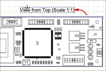
The location of the Title text for placed Views and Tables is now able to be set to a range of positions around the object, or moved to any position by simply dragging the Title text itself.
For Views and Tables, the Title section in the Properties panel includes a Location drop down menu for selecting from a predefined set of Title positions. The default Title position for each type of object is defined through the Draftsman – Primitive Defaults page in Preferences (DXP » Preferences), under the Board Views and Table sections.
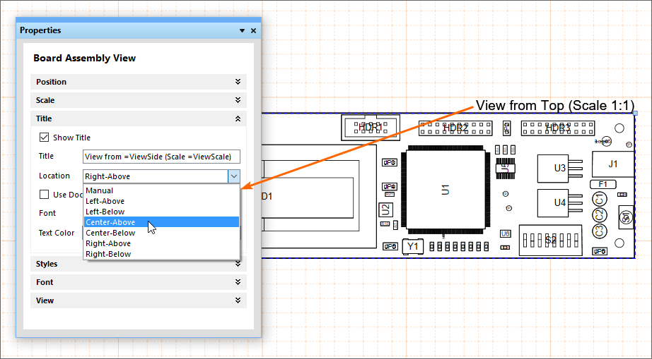
Manually position a Title in the workspace by dragging it to a new location. The Properties panel’s Title – Location setting will automatically change to the Manual option when the Title text has been dragged to a new position.