
Exploring the Browser-based Interface of an Altium 365 Workspace
Parent page: Altium 365 Workspace
In addition to connecting to a Workspace through Altium Designer – interfacing to it through the Explorer panel and Components panel (for direct interaction with the components therein) – you also connect to it through a dedicated browser interface, with access to management interfaces for the various services available as part of the Workspace. Indeed, with some of these services your only interaction with them is through this browser interface.
Accessing the Interface
The browser-based interface to a Workspace is actually presented as a constituent part within the overall Altium 365 Platform Interface. Access to this interface can be performed in a number of ways. Refer to the section Signing in to the Interface, on the Altium 365 Platform Interface page for more details.
What's Provided?
Within the Altium 365 Platform Interface, the area for the active Workspace provides a number of key technologies and services and can be coarsely divided into two groupings, as shown in the following image and listed thereafter.
 The Altium 365 Platform Interface showing the active Workspace.
In the above image:
- Interface elements that can be accessed by any Workspace user. To access a page, click on its name within the left-hand navigation tree.
- Interface elements that can only be accessed by a Workspace Administrator. A user is bestowed administrative powers by membership to the role Administrators. To access a page, choose the required entry within the Admin section of the left-hand navigation tree.
General Access Interface Elements
The following sections summarize the elements of the Workspace's browser interface that can be accessed by all users of the Workspace – both administrators and standard users.
Get Started
This page provides access to a Quick Start Guide of sorts to give you an overview of, and get you up and running with, Altium 365.
 Browse through the documents and videos for getting up to speed with Altium 365, directly from within the browser interface.
Projects
Related pages: Workspace Projects, Management of a Specific Project, Altium Designer Environment
This page provides the interface to the Projects service, to create and manage projects in a central location, in a CAD-centric way, and share those projects for team collaboration as required. The page lists all projects for the Workspace. Workspace-based projects target the development stage of the project lifecycle, simplifying the creation and ongoing workflow for version controlled projects. From here you can create new projects and open and manage existing ones. From this interface a project can also be shared, or rather its access permissions configured.
 Centralized management of your design projects – all part of your Workspace.
Altium Designer projects can be uploaded directly from your PC into the Workspace with the Upload Project option available from the  button menu. In the following browser window, specify a folder containing the project files to upload.
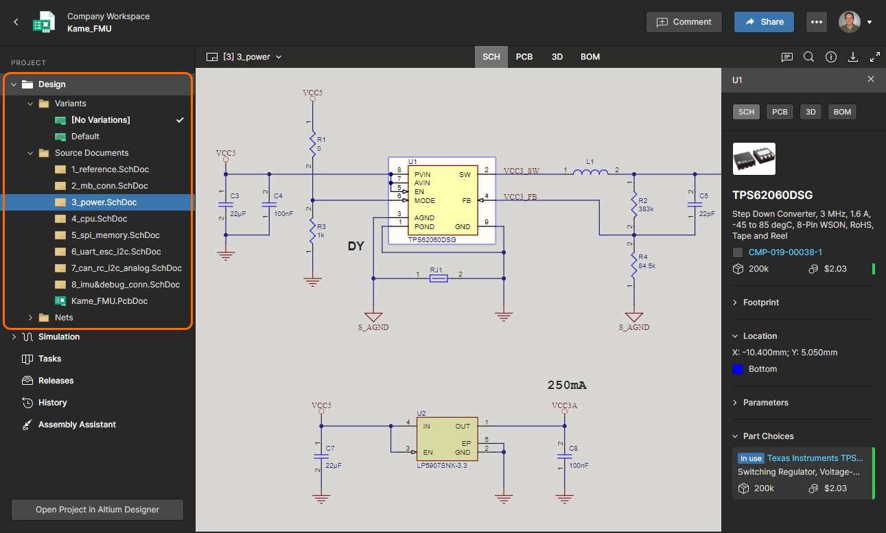
You can also access a detailed, CAD-centric view of the project, opened by selecting the required project, clicking the  control above the listing of projects, and choosing the Open entry on the associated menu. Alternatively, double-click directly on the required project entry in the list (or click on its name). The detailed management page for that project opens in a new browser tab incorporating the CAD-centric interface, which offers Design, Simulation, Releases, History, and Assembly view options:
- Design – display and navigate source project design documents, view design object properties and place review comments. This view uses the Web Viewer interface to present your design across five distinct data sub-views, to show the source schematic(s), board in 2D, board in 3D, Draftsman document and Bill of Materials respectively. This view is for the latest version of the source project data, rather than a specified release from that project, and so could be considered to be a work-in-progress (WIP) view. You can review both the base design and any defined variant thereof.
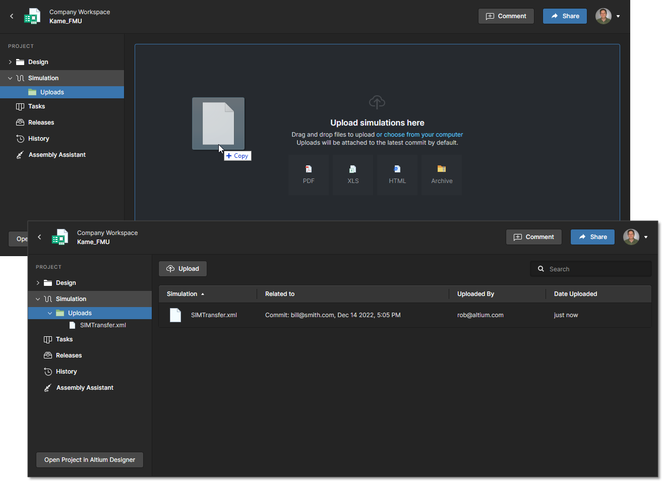
- Simulation – allows you to upload circuit simulation results files that will be associated with the current project or project Release. The files are effectively attached to the project, which allows members of the Workspace to inspect and/or download simulation results documents that relate to the currently open project. See Management of a Specific Project – Simulation for more information.
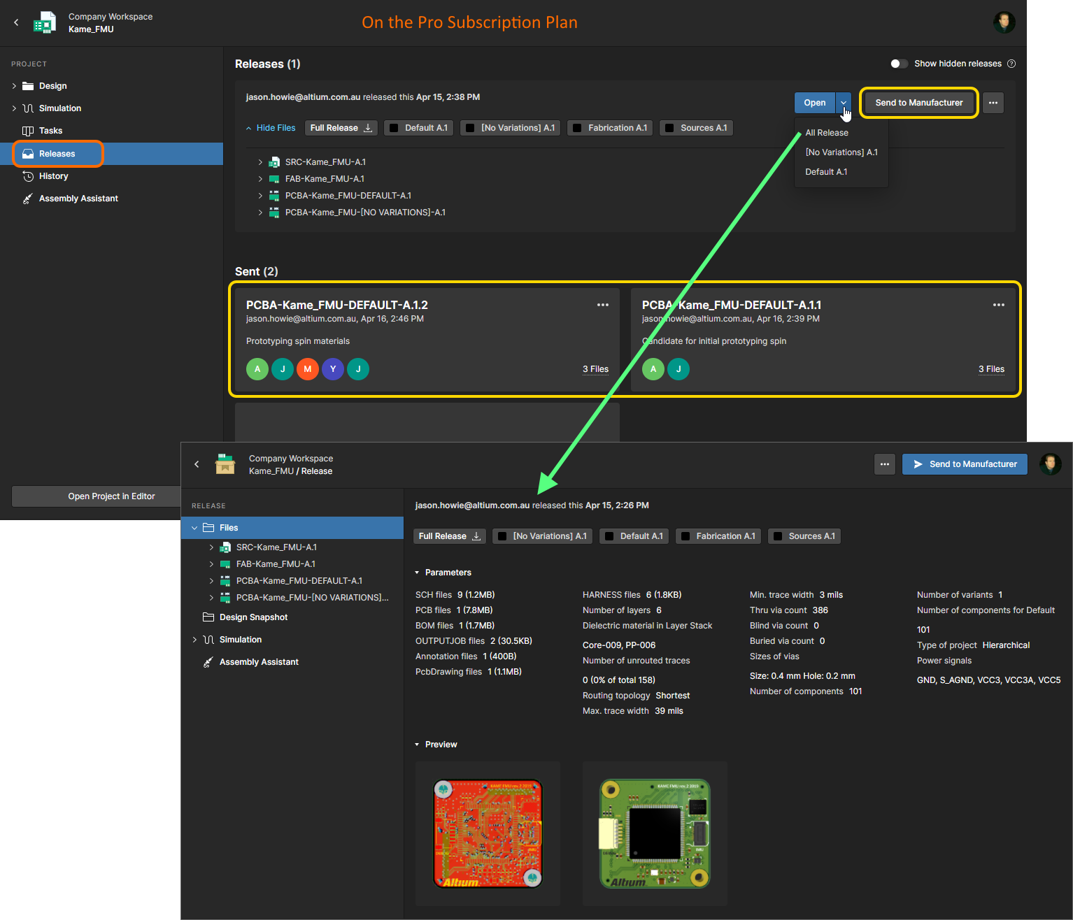
- Releases – view the releases for the project. Access is provided for opening the full release data, or a specific assembly package, which will be presented on a separate tab through a Manufacturing Portal. From this portal you can view and navigate the released file data, inspect the BOM, and view and comment on the snapshot of the design itself; the source for that released data. From either the Releases view, or through the Manufacturing Portal for a specific release, you'll have access to controls for downloading manufacturing data at various levels of granularity (from full data set(s) to individual generated output files). A chosen release can also be sent – as a Manufacturing Package – directly to your manufacturer. You even have the ability to compare Gerber data between releases or against a locally-generated file set, and compare Schematic data or BOM data between releases.
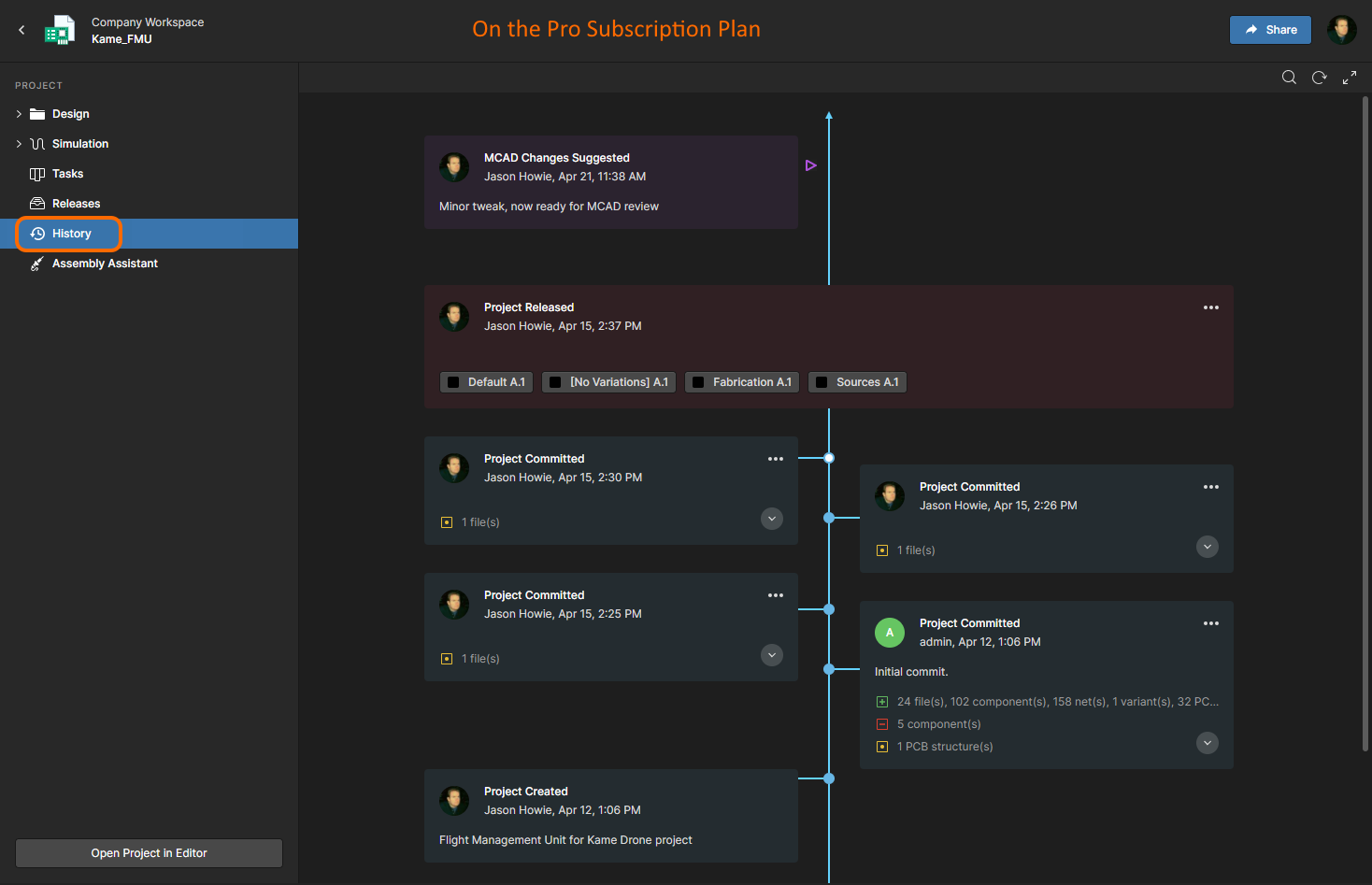
- History – browse a progressive timeline of major events relating to the project, including its creation, commits, releases, clones and MCAD exchanges. Each time a supported event happens in association with the project, that event is added to the timeline as a dedicated tile with various actions supported where applicable. For release events, you also have the ability to compare BOM data between releases and compare Gerber data between releases or against a locally generated file set. Detailed Schematic comparisons are available between commits and/or releases.
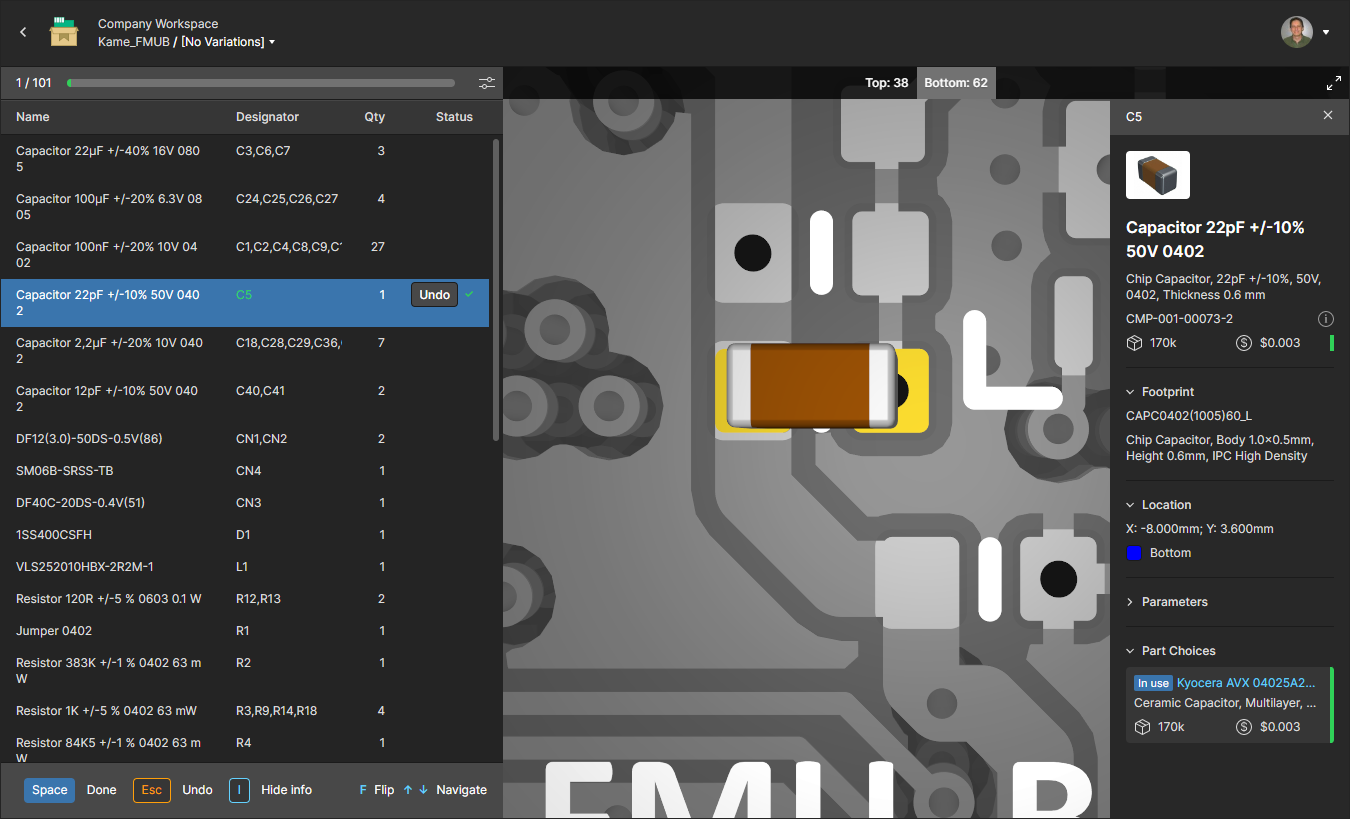
- Assembly – work with the interactive Assembly tool to check and progress through the board assembly process. The tool brings together the project's detailed BOM data and its 2D/3D assembly view to present an interface that provides the required set of graphical and component part information for stepping through the assembly process. See the Assembly App page for more information.
Components
Main page: Workspace Components
This page gives you convenient access for browsing all of the components that are currently stored within your Workspace. Not only can you quickly see which (and how many) components you currently have at your disposal (and gain detailed information about each and every component), but you can also view a summary of the health of those components. Delving deeper, you have access to view more detailed information regarding component health, through a dedicated Library Health dashboard. This provides greater detail on issues, and enables you to quickly assess and fix components accordingly.
The page is comprised of three regions, as shown in the following image and listed thereafter.
 Browse the components currently available within your Workspace from the Components page of the browser interface. The Library Health region provides a summary of the components and their health.
The Components page, as indicated in the above image, is comprised of three regions:
- Library Health – this region of the page provides a summary of the health of your components since last running a health check. Access is provided to the detailed Library Health dashboard page, from where you can run health checks and inspect component health issues in greater detail.
- Components – when the page is first accessed this region presents a tiled array of the various component types, along with the total number of existing components of each type. From here you are able to drill down to see individual components and get detailed information about them.
- Supply Chain Data Sources – this region of the page lists the supply chain data sources that are used. By default, your data source is Octopart. If you have a higher level of Altium software access, you also benefit from IHS Markit Parts Intelligence (and others) and the ability to connect to your own internal company parts database. For more information on these sources, see altium.com/part-data-sources.
Used Parts
Related information: BOM Portal, Workspace Components.
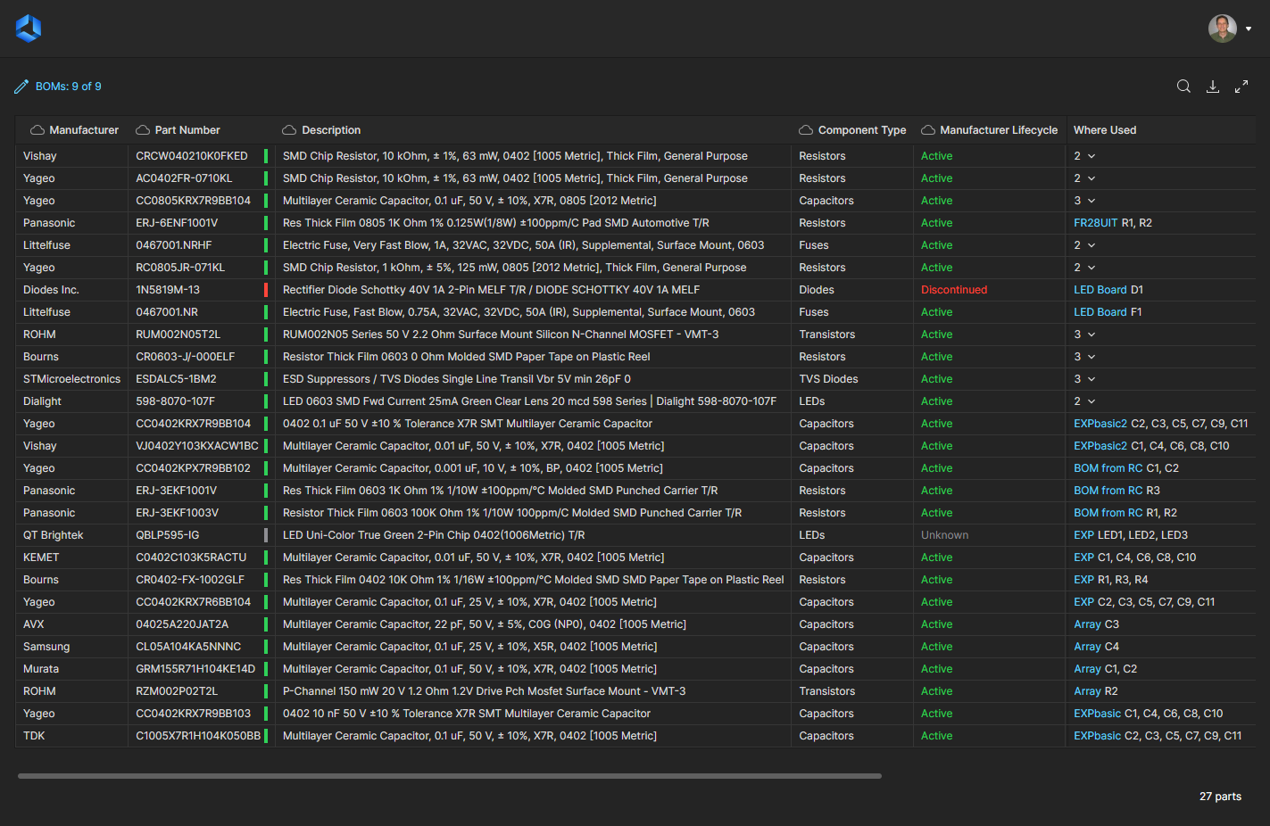
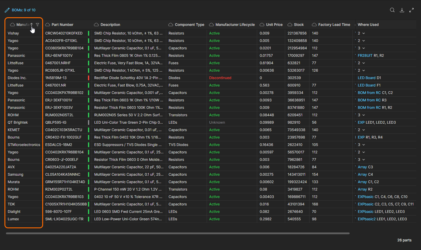
This page provides an aggregated overview of all manufacturer parts that are currently used in Workspace Managed BOMs. The listing is populated with key parameter columns (including SiliconExpert parameters if available) for each manufacturer part item, and includes active Where Used links to the referenced BOM document. The Used Parts page report allows you to quickly view all manufacturer part references that are applied in design BOMs while checking for active issues such as inappropriate Lifecycles, lack of standards compliance, or an extended manufacturing lead time. Note that the current report view can be saved as a CSV file using the download function ( ).
).
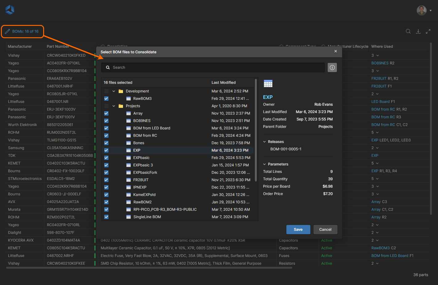
All Workspace Managed BOM documents are included in the report by default, the number of which is indicated by the BOMs entry link above the parts report list. Select this link to open the Select BOM files to Consolidate dialog window to manage which BOM documents are included in the report. Use the list checkboxes to isolate the BOMs of interest, and enable the window’s Information pane ( ) to view the details of a selected BOM (or folder).
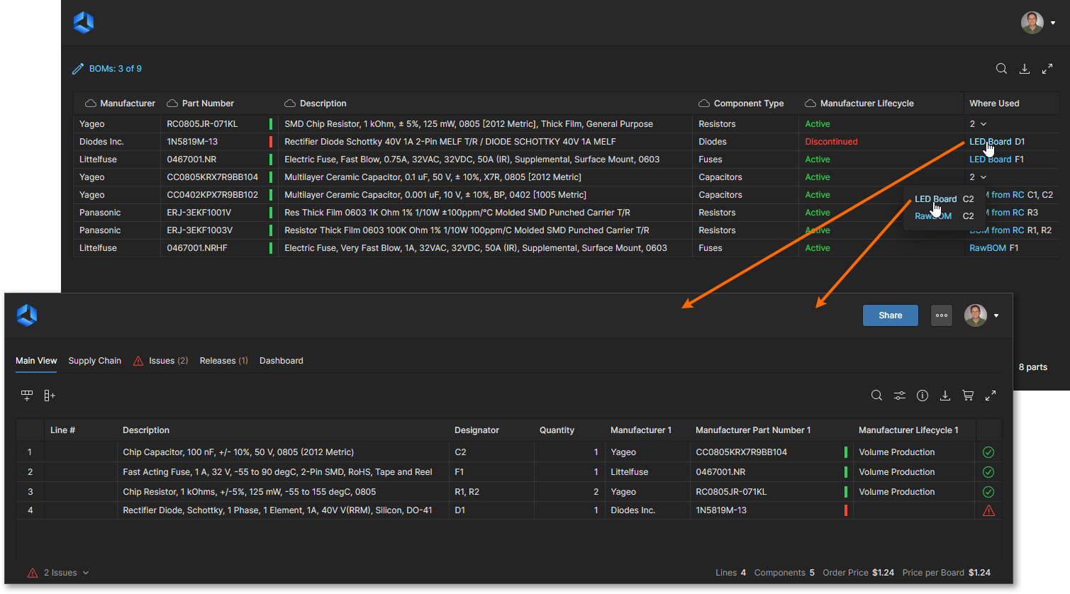
The report’s Where Used column includes both the associated BOM name and referenced component designators. Where a part is used in multiple BOM documents, the Where Used cell will include a drop-down list of those BOMs and related designators. Select a BOM name to open that BOM document in a new browser tab.
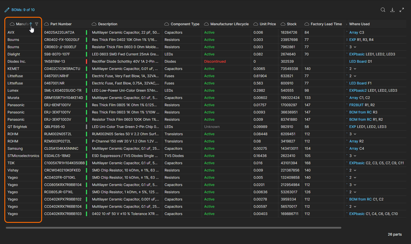
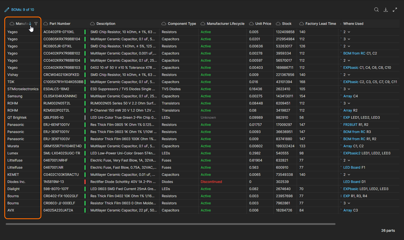
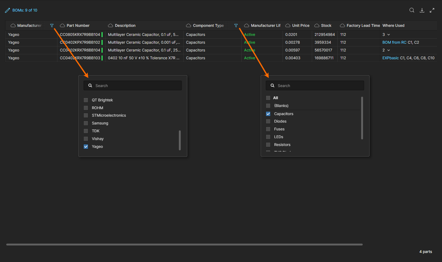
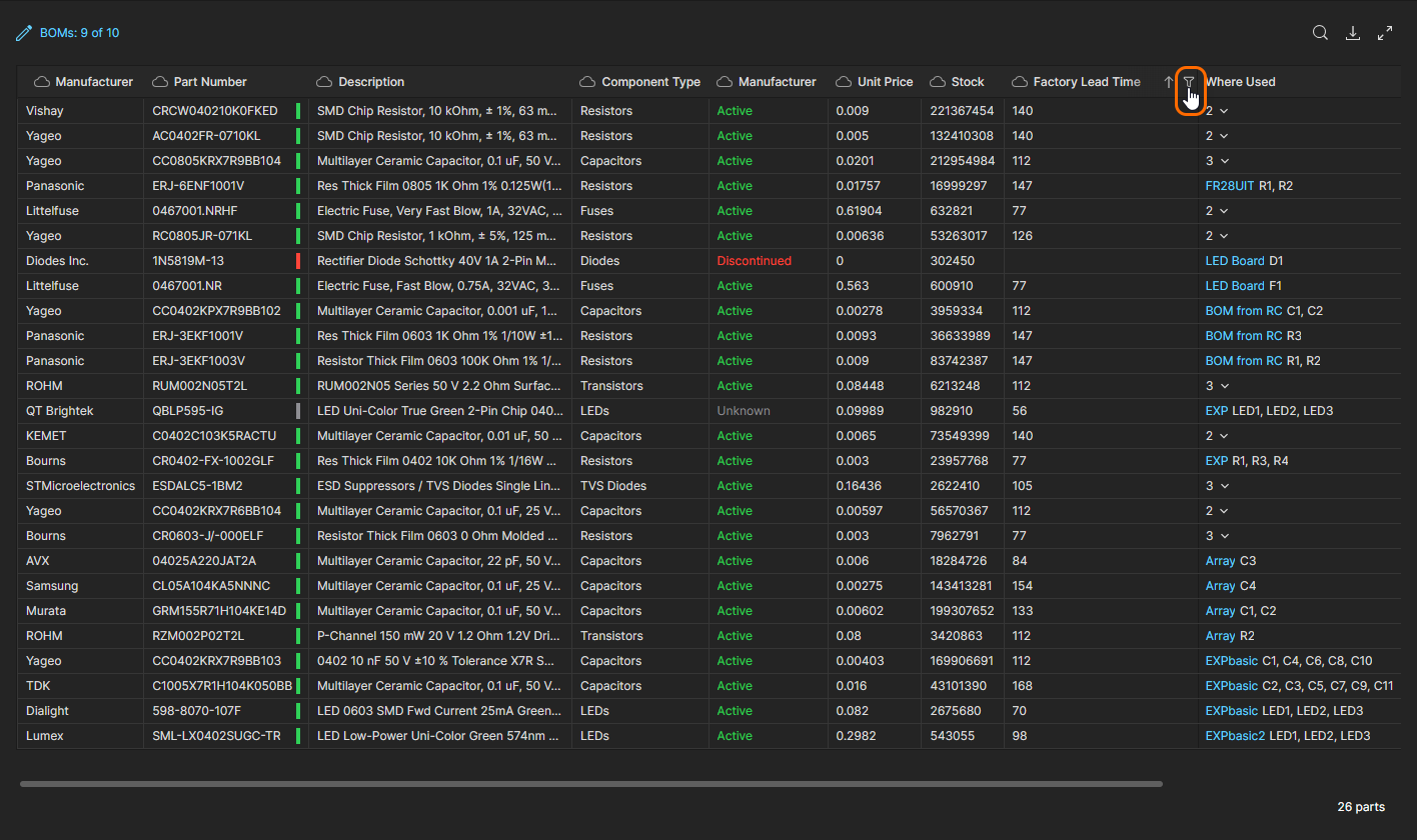
The Used Parts interface offers a range of features for locating the information you need for auditing parts usage. These include column ordering, keyword searches and advanced data filters. When used in combination, these features offer a high degree of control over which entries are included in the Parts report and how they are presented.
- List order - Order the Used Parts list entries by a specific set of parametric data by toggling the arrow option in that data column’s header. Click a header’s
 icon to reorder the parts list in ascending order by that dataset, click again for the descending data order, and click once more to remove the list order defined by that column data.
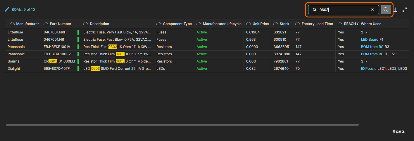
- Search – Limit the parts list entries to those that include keywords entered in the Search field, which is opened (and closed) with the
 icon. The search is case-insensitive, includes all part parameter columns (except
Where Used), and highlights the found search terms in the listed results.
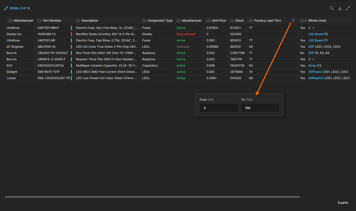
- Filters – Constrain the parts list to entries to those that satisfy specific parameter data requirements set by column Filters. A Filter is configured in a column header’s
 drop-down menu by checking one or more of the available parameter values, or for numeric parameters, by setting a From/To number range. Use the All option to toggle all checkboxes on/off, the Blank option (if available) to disable/enable entries where a value is not included, and the Search field to locate a specific value option. Note that multiple Filters can be enabled to tightly curate the report results.
|
Configure parameter data based Filters from the related column’s Filters also may be applied to parameter datasets that are numeric rather than textural, such as With numeric parameter filters, enter the range of values that will be accepted for inclusion in the parts report entries. Note that the From and To labels also indicate the minimum and maximum values without a filter applied. |
Tasks
Related information: Working with Tasks, Web Viewer Commenting Window.
This page view allows you to access and manage all Tasks – job activity requests – that are currently active in the Altium 365 Workspace. Tasks are presented in a Kanban board flow style, with their progress state (ToDo, InProgress and Resolved) moving through Task rows. One row is reserved for general Tasks (those not associated with a project), and each remaining row applies to Tasks for a specific project. General Tasks are created from within the dashboard, and Project-specific Tasks are created by assigning a Workspace member to a project Comment.
 Manage and work with collaborative job activity Tasks through the Altium 365 Workspace Tasks dashboard.
Although presented through a relatively simple interface, the Workspace Tasks dashboard offers a flexible and efficient way of both managing and tracking workflows within the actual design environment rather than via an external system. This page is a global view of all Tasks that are currently active in the Workspace, while the project-specific Tasks view available from the navigation tree when viewing a project represents only those Tasks associated with that project.
MCAD CoDesigner
Related page: ECAD-MCAD CoDesign
This page relates to ECAD-MCAD CoDesign functionality. MCAD CoDesigner synchronizes the PCB design between electrical and mechanical engineers. It works directly with ECAD and MCAD data via the MCAD CoDesigner panel on the Altium Designer side, and a corresponding panel plugged into your MCAD software. The latter is provided through installation (and registration to the MCAD software) of the Altium CoDesigner plugin.
The following MCAD platforms are supported when using the latest Altium CoDesigner plugins:
- Dassault Systemes SOLIDWORKS®
- Autodesk Inventor Professional®
- PTC Creo Parametric®
- Autodesk Fusion 360®
- Siemens NX®
The versions of MCAD tools officially supported will depend on the version of Altium CoDesigner plugin being used. This information can be found on the New in CoDesigner page.
 The MCAD CoDesigner page provides an overview of the area, along with links to the MCAD CoDesigner Plugins and further educational material.
The page offers the following:
- A control to play an Overview Video.
- Highlighting of which MCAD Software platforms are currently supported.
- A Link to the MCAD CODESIGNER PLUGINS section on the Downloads page of the altium.com site, for access to the plugin required to add this co-design functionality to your MCAD design software installation.
- Quick guidance on how to start collaborating from the ECAD or MCAD side – hover over the
 control.
 - Links to further documentation and how-to videos. The latter is to YouTube, but the videos can also be found here within the documentation.
Part Requests
Related page: Part Requests
This page enables you to create and manage requests for new components. An engineer can simply put in a request for one or more parts to be created and get notified when that request has either been completed, and the component(s) made available, or rejected (and why). The requestor supplies as much key information to support their request as possible (manufacturer and part number(s), description(s), any relevant datasheet (PDF or URL)). Stub Component Items can even be created that the librarian can then run with (and finish off).
 Adding a new part request through the Workspace's browser interface. Hover over the image to see the form presented to receive the details of the request.
Workspace Members
Related page: Managing Workspace Membership
This page is used to create and manage a list of Workspace users – people who are members of the Workspace and have access to the Workspace and/or its associated technologies.
User members can be those with AltiumLive accounts within your own organization, or those in a different organization (in the case of the latter, inviting them in as members of a Workspace does not mean they become part of your organization). You also can invite users who do not have an AltiumLive account (who will need to then register for one). Users can submit a request to join your workspace, and existing users can submit a request for another user to be invited to the Workspace.
 Determine which people are to have access to the Workspace from the Workspace Members page of the interface. Hover over the image to see the view for non-administrators.
The tab options at the top of the page allow administrators to view all users with access to the Workspace, and manage any users requesting access to the Workspace:
- Members – all users with member access to the Workspace based on their applied Role membership and applied access permissions. This is the default view and the only option available to those not in the Administrator Role group.
- Guests – users who are external to the organization Workspace (non-members) that have been granted shared access to a Workspace project. Such users are indicated by an associated
 icon.
icon. - Join Requests – request submissions by users of your organization who are seeking access to the company Workspace.
- Invitation Requests – request submissions by members of the Workspace for allowing access to the Workspace by another user, or users.
 ). Use the Search field to quickly find a member within the list.
Trash
This page presents all items that have been 'soft deleted' – items that have been deleted, but not yet permanently so. The Trash is essentially a recycle bin into which any item within your Workspace can be moved (through a soft delete action). It is isolated from the rest of the Workspace and so any item in the Trash is not available for use and cannot be found through searching, or through pages in the browser interface, or from within Altium Designer.
 When you delete an item in the Workspace through a soft delete action, it will be moved to the Trash. The Trash page provides the interface to this isolated area of the Workspace.
You will only see items that you yourself have soft deleted. An administrator will see all soft deleted items in the Trash. Each item is presented in terms of the following information:
- Its content type icon
- Its name
- Its description
- Its revision
- By whom it was deleted
- The date and time at which it was deleted (sent to the Trash).
Select an item in the Trash, then use the controls at the top-right of the list to permanently delete that item, or to restore it, respectively. Corresponding commands are also available from the menu associated with the ![]() control (at the far right of the selected item).
control (at the far right of the selected item).
.") Select an item, then decide whether to fully restore it for use again, or to permanently delete it (a 'hard delete' if you will).
Select an item, then decide whether to fully restore it for use again, or to permanently delete it (a 'hard delete' if you will).
Alternatively, to empty the entire Trash in a single, batch action, click the ![]() button at the top-left of the page. A confirmation window will appear alerting you to the fact that this action will delete all items permanently and that they cannot be restored thereafter. To proceed click the
button at the top-left of the page. A confirmation window will appear alerting you to the fact that this action will delete all items permanently and that they cannot be restored thereafter. To proceed click the ![]() button.
button.
Admin-Only Interface Elements
The following sections summarize the elements of the Workspace's browser interface that can only be accessed by Administrative users of the Workspace – those who are part of the Administrators role. Access to these elements is through the dedicated Admin area of the left-hand navigation tree.
Admin – Settings
This page provides a collection of sub-pages for the configuration of options relating to various features and services provided by, and through, a Workspace.
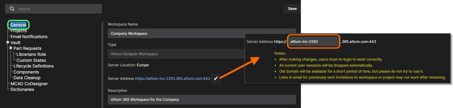
 The Admin – Settings area, part of the admin-only pages within the Workspace's browser interface. Hover over the image to see the interface for the minimal level of access.
The left-hand side of the page provides a navigation tree with which to quickly access various sub-pages of settings. The following pages are available:
- General – use this page to change the name, server address and description for the Workspace as required. The page also provides read-only information about the Workspace's type and its location. Changes can only be made by the Administrator who is also the Owner of the Workspace and not by any other Administrator of that Workspace.
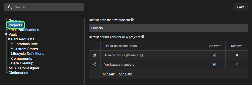
- Projects – use this page to specify the default path (within the Workspace's folder structure) for newly-released projects. You can also define default sharing permissions for new projects, so that the right users and/or roles have access to those projects from the moment they are created.
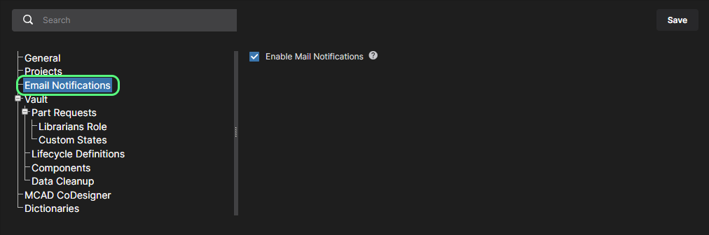
- Email Notifications – this page provides a control to enable the Workspace's email notifications feature. This facility flags a variety of events to key stakeholders, relating to component Items, projects and part requests.
► See the Email Notifications page for more information.
- Vault – not a page, but rather a structural entry for gathering together settings related to specific functionality within the Workspace itself.
- Part Requests – a structural page to gather the following sub-pages related to the Part Request feature:
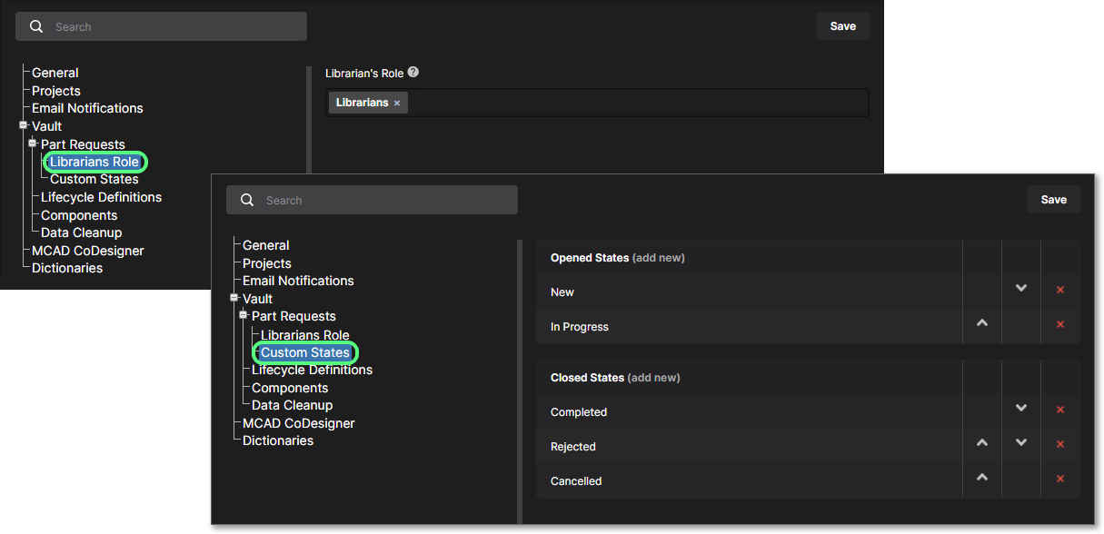
- Librarians Role – use this page to specify which role (or roles) should be used to fulfill the role of Librarians for your organization. In essence, you are simply configuring a set of users of your Workspace that can be assigned to a part request. The sample role Librarians will already be prefilled here.
- Custom States – use this page to customize opened and closed states for the Part Request feature.
- Part Requests – a structural page to gather the following sub-pages related to the Part Request feature:
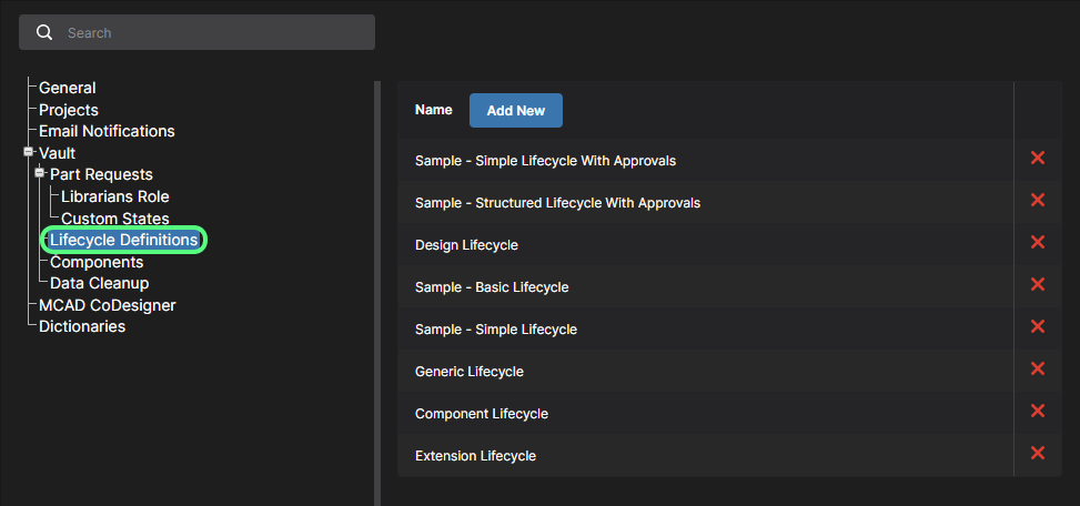
- Lifecycle Definitions – use this page to define and manage your Workspace's lifecycle definitions, complementing the ability to do this through Altium Designer. Providing better visibility of the states and transitions involved, each lifecycle is built in a graphical way to show the flows involved.
- Components – use this page to define default target folders in which new models should be created, when creating a new component in the Workspace. To change a default folder, click the
 button. The Explorer window will appear with which to choose the desired new default target release folder for that model type. Once chosen, click OK to close the window and return to the Components page, with the applicable field updated with the new folder path.
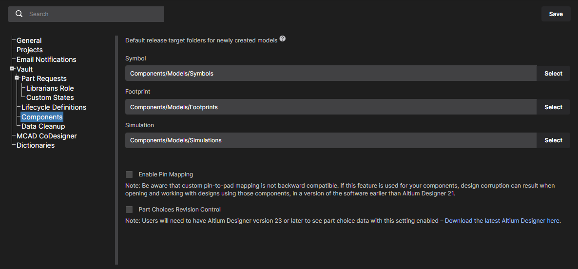
This page also includes options for enabling additional features that will become available when editing Workspace-based components in Altium Designer (click  to confirm a changed setting):
- Enable Pin Mapping – When enabled, the pin mapping functionality is available when editing a component in Altium Designer's Component Editor (in its Single Component Editing mode). Mapping is driven through the dedicated Pins panel. By default, the numbered pins of the symbol will be mapped to the same numbered pads/pins in the referenced footprint and simulation models. Change the mapped pad/pin targets directly by clicking on a cell of the model and entering the required value. This allows for custom pin mapping.
- Part Choices Revision Control – When enabled, Altium Designer's Component Editor (in its Single Component Editing mode) will open when editing a Workspace-based component's Part Choices List, instead of the Edit Part Choices dialog. This allows a new component revision to be created in response to a changed Part Choices List, providing more formal (and traceable) control of manufacturer Part Choices data – see Part Choice Revision Control for more information.
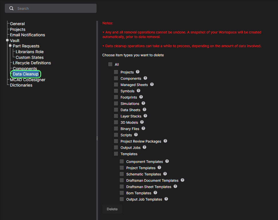
- Data Cleanup – use this page to quickly delete data items from your Workspace. This is particularly useful after having experimented with creating and releasing content into your Workspace, for example when trying out the migration of unmanaged libraries, and now you want to 'flush' such experimental data. This functionality works on any and all Item types in your Workspace.
Use the available checkboxes to determine whether to delete all data items (All) or specific item types. With your cleanup strategy configured, click the  button. A window will appear asking for confirmation, and alerting you to the fact that this action cannot be undone. To verify and proceed, enter the text Delete my data permanently into the field and then click
  .
.
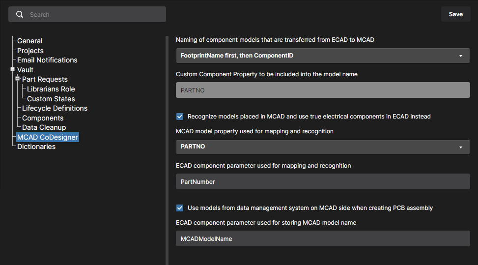
- MCAD CoDesigner – this page provides controls to enable component recognition between the ECAD and MCAD domains, when using the ECAD-MCAD CoDesign feature. This facilitates the use of native components when a design is pushed and pulled between the two domains. The following options are available.
- Specify how transferred ECAD models are named – set the naming convention used for models during the initial transfer to the MCAD domain. This is set to
<FootprintName><ComponentID>by default, and can be changed to<ComponentID><FootprintName>or<CustomComponentProperty><FootprintName>.In the latter case use the Custom Component Property field (otherwise set toPARTNO) to define the custom property you wish use in the MCAD component name. This option allows engineers to include meaningful information, such as detailed part number data, into the component identification. - Recognize models placed in MCAD and use true electrical components in ECAD instead – enable this option to support use of native components when the board is being Pushed from MCAD and Pulled in to ECAD. The MCAD 3D model is linked to the equivalent Altium Designer component, so when the board is pulled into Altium Designer the MCAD 3D model can be replaced by an instance of the fully-defined Altium Designer component footprint, complete with a 3D model. Use the two sub-fields to determine the MCAD model property and the ECAD component parameter, used to identify components in the two design domains. By default, these fields are populated with the entry PARTNO. The MCAD model property can be your own custom property, or choose MCAD model name from the drop-down. The ECAD component parameter can also be your own custom parameter. These fields are required if the parent option is enabled. If one or both are left blank, the button will be disabled.
- Use models from data management system on MCAD side when creating PCB assembly – enable this option to support use of native components when the board is being Pushed from ECAD and Pulled in to MCAD. The MCAD software gets the model of the component from the MCAD's data management system (by the model’s name) and then places that component on the MCAD PCB assembly, instead of the model that came from ECAD. Use the sub-field to determine the ECAD component parameter that will be used to store the MCAD model name.By default, this field is populated with the entry MCADModelName. This field is required if the parent option is enabled. If left blank, the button will be disabled.
- Specify how transferred ECAD models are named – set the naming convention used for models during the initial transfer to the MCAD domain. This is set to
- Dictionaries – use this page to create custom parameters with several defined values (Dictionaries) that can be applied to Component Templates through Altium Designer. Multiple parameter Dictionaries can be added, with each entry containing a listed choice of corresponding parameter values. When used, this approach provides a more formalized control over the application of parameter data, where standardized parameters and their value choices are centrally managed in one accessible location.
 Create predefined lists of parameter values using the Dictionary option under Admin - Settings.
To add a Dictionary entry, click the  button and then enter an appropriate parameter type name in the following Create Dictionary window. Add parameter values using the
  option associated with the Dictionary entry's name – press
 Enter to confirm the entered value.
 Multiple Dictionaries can be created with multiple parameter values.
 option to delete a value entry or the Dictionary entry itself.
In Altium Designer, Dictionaries created in the Altium 365 Workspace become available as Parameter data Types when creating or editing a Component Template. Where that Template is used for creating a new component – or when editing a component based on that Template – the Dictionary-defined parameter entries will offer only those value choices defined in the Workspace Dictionary. Note that Dictionary-based parameters are indicated by their associated icon.
► For more information, see Support for Dictionary-defined Component Parameter Data Types in Altium Designer's Component Editor.
Admin – Roles
Related page: Managing Workspace Membership – Roles
This page is used to create and manage a list of roles; roles allow you to further organize your user members according to, for example, the particular section of the organization in which they are involved, or the design team they are in. Roles also make the sharing of Workspace content, and the configuration of other served technologies, more streamlined.
 Access and manage the roles defined for your Workspace from the Admin – Roles page of the interface.
Admin – Part Providers
Related page: Part Source Configuration
This page enables you to define a Part Source – facilitating centralized supply chain management, with designers across the entire organization using the same approved list of Suppliers, with which to source supply chain intelligence for parts used in their designs.
The following part sources are available for a Workspace:
- Altium Parts Provider – an aggregate supplier data service that provides access to live component information from a comprehensive range of parts suppliers.
- Custom Parts Provider – for situations where component supplier data is (and must be) sourced from an internal company enterprise system that provides a proprietary set of parts supplier data, which might be based on a tightly approved range of vendors and/or special pricing structures. This part source is actually configured for synchronization through Altium Designer – using a Custom Parts Provider Synchronization Configuration document (*.PrtSync) – allowing the supplier data from a specified database source to be mapped to Workspace supply chain data.
The actual supply chain intelligence – comprising Manufacturer (and part number), Supplier (and part number), Description, Pricing and Availability – is sourced from the Workspace's local Part Catalog and the relevant Part Source.
 Enabling required Suppliers and determining Location/Currency ranges for the Altium Parts Provider.
Admin – PLM Integration
Related page: PLM Integration
This page provides the interface to the Altium 365 Workspace PLM Integration service. It is from here that you define the interconnection with a PLM instance and enable/configure synchronization of your PLM components with those in the Workspace.
The Workspace facilitates the uni- or bi-directional synchronization of component data with your company enterprise systems. Interaction between the Workspace data and the enterprise system – typically a PLM system – is configured and managed through the PLM Integration page. This provides an automated interface for easily configuring the interconnection, mapping parameter data, and specifying the direction of data synchronization. Component data synchronization between the Workspace and target enterprise system uses a built-in synchronization process which may be manually triggered or set as a timed repeating event.
The Workspace provides support for the following PLM systems:
- PTC Windchill® PLM version 12, and PTC Windchill+ (Windchill's SaaS variant).
- Arena® PLM.
- Oracle® Agile™ PLM.
- Aras Innovator® release 12.0 SP18.
- Siemens Teamcenter®, with additional integration setup.
- Duro PLM, implemented as a third-party PLM instance.
 PLM integration setup is performed through an automated interface for easily configuring the interconnection, mapping parameter data, and specifying the direction of data synchronization.
Admin – Processes
Related pages: Creating & Managing Processes, Defining a Process Workflow
This page provides the interface to create and manage Process Workflows that formally guide a company's designers through typical, everyday design processes such as:
- Requesting new library parts.
- Performing project-related activities, such as design reviews or publishing to a PLM.
- Creation of new projects.
Each Workflow that is used to implement a particular design process is created as part of a Process Definition. It can therefore be referred to as that process's underlying Workflow, or simply a Process Workflow. Processes and their Workflows are created and managed through the Processes page interface, where a range of predefined processes can be enabled for use or cloned and modified to suit your needs using the included Process Workflow Editor.
 Use the Browser tab to browse all active and closed processes and the other tabs to view, create, and manage the available Process Workflows.
Admin – Explorer
Related page: Managing Content Structure & Access
This page gives you access to the structure of the Workspace, and is similar in presentation and layout to that of Altium Designer's Explorer panel. From here, you will be able to browse the folders and Items within the Workspace. And although you can't create or edit Items from within the browser interface (you can remove them), you are able to create and edit folders, and so build the structure of the Workspace, without having to be connected to that server through Altium Designer.
You also can define folder-level and Item-level sharing from this interface – controlling who is able to see what content in the Workspace and, at the folder level, whether other users can simply view a folder and its content, or also edit it (effectively releasing/committing/uploading design data into it). Content can be downloaded from the Workspace, directly from this interface.
 Browse and define the structure of your Workspace as well as defining access to, and being able to download, content therein.
Admin – Apps
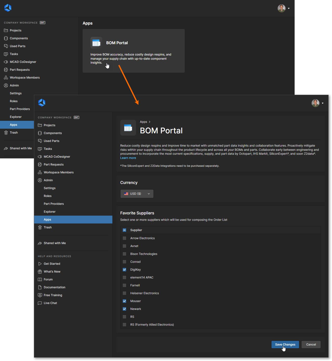
This page provides setup access to additional licensed applications – software services and extensions – available in your Workspace. Applications (Apps) are presented as selectable tiles, which provide access to additional information and configuration options for that service.
Click on an App tile to launch the application’s setup view, where you can specify its connection credentials and any associated settings as required.
BOM Portal Application
The Altium 365 BOM Portal application allows you to create data-rich BOM procurement documents from Workspace design projects or uploaded (CSV/XLS) ECAD BOM files. Using Altium’s comprehensive data services, the Portal’s Managed BOM documents include up-to-date component manufacturer information and live Supply Chain data from multiple sources. The web-based system is automated, highly configurable, and offers advanced search capabilities for determining the optimal component parts for your design projects.
Select the BOM Portal application tile – available when the feature is enabled – to open its setup page. Use the page options to specify the default currency and part supplier vendors available for newly created/uploaded Managed BOM documents. The currency and enabled suppliers can be changed from these defaults in individual Managed BOM documents through the BOM Settings window. Note that the available suppliers included in the Favorite Suppliers list are in turn defined by the Altium Parts Provider settings in the Workspace Part Providers page.
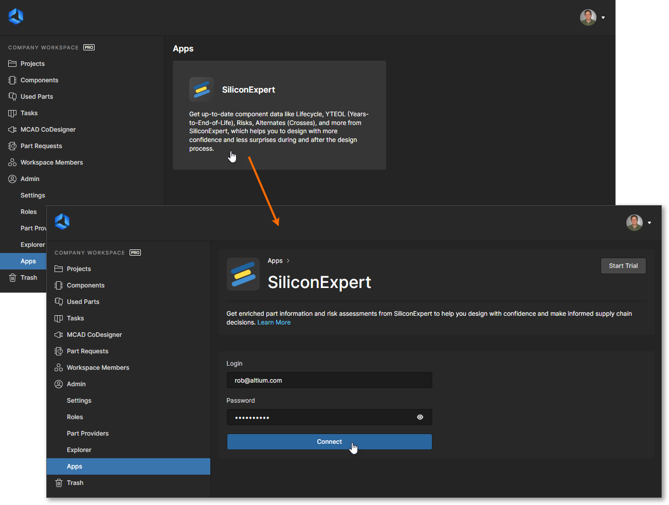
SiliconExpert Application
Altium 365 SiliconExpert Integration provides direct access to an additional set of advanced manufacturer parts data that is available to your BOM Portal documents, project BOM documents and the Library Health analysis. The enhanced parametric data sourced from SiliconExpert populates Workspace BOMs as specific parameter columns (YTEOL, Inventory risk, etc). SiliconExpert's advanced parametric parts data and ranked alternative part suggestions are also available when accessing Supply Chain Information features in Altium Designer.
This application is fully available for use when you have purchased an Altium SiliconExpert Integration license. To enable this service, open the SiliconExpert application by selecting its tile, enter the credentials provided to you by Altium, and then confirm the settings ( ). Also note that you can sample the benefits of integrating SiliconExpert with your Workspace by activating a trial period (
 ).
).
Once your SiliconExpert service connection is established, the SiliconExpert Integration view will be populated with information relating to your account. This includes a configurable list of reporting levels and parameter data:
- Information in the Part Quota Details section includes your current SiliconExpert parts data quota limits and usage.
- The Checks Manager section includes the default Report Level settings for SiliconExpert parameter values. Use the drop down list associated with each entry to choose a different reporting level (
Fatal/Error/Warning) or theNo Reportoption to prevent a value condition from being reported. Note that you also can edit the Years to End of Life values (in years) that will trigger the threeYTEOLreport levels. - The Data Visibility Settings list includes all SiliconExpert parameters available to you. Use the parameter checkboxes to toggle their visibility in parts data listings (project BOMs, Managed BOMs, etc) for both Altium Designer and your Altium 365 Workspace – hover over
 icons associated with parameters to see related information. Note that the base SiliconExpert
 YTEOLandLifecycleparameters are always available, and their visibility state cannot be toggled.


Scroll to view the full SilicconExpert configuration options.