
定义板形外框
The Board Shape defines the boundary, or extents, of the board in the PCB Editor. The Board Shape is a PCB object that is also referred to as the Board Outline and is essentially a closed polygon. When you create a new PCB document, it is the black area with the visible grid showing inside (assuming the grid is coarse enough to see at the current zoom level).

The default 6" by 4" board
The Board Shape is used by Altium Designer when:
- Splitting a board into multiple board regions.
- Placing bending lines on a flex board region.
- Defining the extents of the power planes for plane edge pull back.
- Splitting power planes.
- Calculating the board edge when outputting design data to other tools.
When a new board file is created, the default Board Shape is sized 6000 x 4000mil. The shape can be resized, or redefined, in a variety of ways. Note that PCB documents created using PCB templates have the Board Shape already correctly sized. Regardless of the final make up of the board (single rigid area or multiple rigid-flex sections), the overall outer shape is referred to as the Board Shape.
Creating and Modifying the Board Shape
The Board Shape can be redefined:
- Manually - by redefining the shape or moving the existing board vertices (corners). Switch to Board Planning Mode (View » Board Planning Mode) then use the Redefine, Edit or Modify Board Shape commands in the Design menu.
- From selected objects - typically done from an outline on a mechanical layer. Use this option if an outline has been imported from an MCAD tool as a DWG/DXF file. Switch to 2D Layout Mode (View » 2D Layout Mode), select the primitives on the mechanical layer (Edit » Select » All on Layer), then use the Design » Board Shape » Define from selected objects command.
- From a 3D body - use this option if the blank board has been imported as a STEP model from an MCAD tool into a 3D Body Object (Place » 3D Body). Switch to 3D Layout Mode (View » 3D Layout Mode) then use the command in the Design » Board Shape sub-menu to select the Board Shape.
Importing an Outline to Use for the Board Shape

Ensure that the scale, default line width, and layer mappings are configured when importing DXF/DWG data.
By combining the ability to import DXF / DWG data into a mechanical layer and then defining the board shape from selected objects, a shape defined in a mechanical CAD package can be transferred into the PCB editor.
To import a DXF/DWG file into a newly created PCB:
- Select File » New » PCB. A new blank PCB will open, the black region represents the current Board Shape.
- Before importing a new shape, set the following as required to suit the requirements of your design and the shape being imported:
- The Units - set in the Other section of the Properties panel in Board mode.
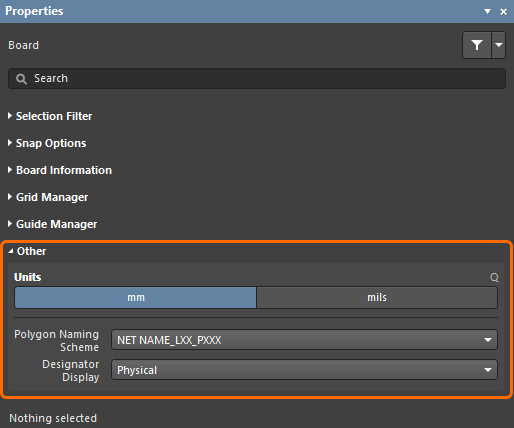
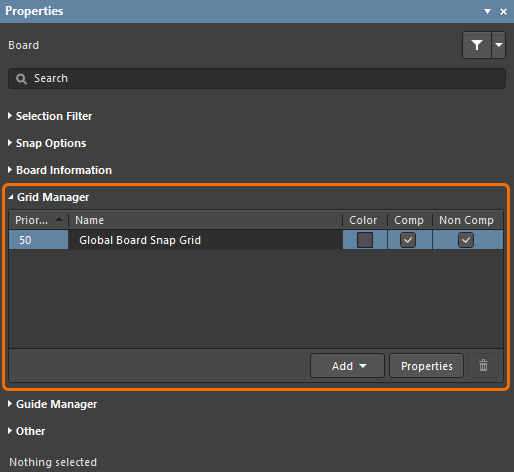
- The Grid - set in the Grid Manager section of the Properties panel in Board mode.
- The Origin - For a new PCB the default location for the user-definable origin is at the absolute origin, the bottom left of the workspace. Select Edit » Origin » Set from the main menus then click to define the location of the user-definable origin, for example the bottom left corner of the current board shape. It helps to set this to suit the location of the origin in the incoming outline.
- The next step is to import the board's shape as a .DXF or .DWG file. Please note that the shape to be imported must be a closed shape and internal cutouts are not automatically created (but can be defined later from imported objects). Select File » Import » DXF/DWG to open the Import File dialog, ensure the File Type on the bottom right of the dialog is AutoCAD Files (*.DXF,*DWG) then browse to find the required file.
- When the Open button is clicked the Import from AutoCAD dialog will open (as shown in the second image on this page).
- Set the Scale, Default Line Width and Layer Mappings as required then click OK.
- Each DXF/DWG object will be mapped to an object and will be displayed in the workspace.
If there is a closed boundary defined on a mechanical layer, it can be use to define the board shape.
Defining the Board Shape From Selected Objects
As mentioned, once an enclosed boundary of line and/or arc objects has been defined, these objects can be used to create the board shape.
To define a board shape from these objects:
- Set the View mode to 2D Layout Mode (View menu).
- Select the objects (the Edit » Select » All on Layer command is ideal for this).
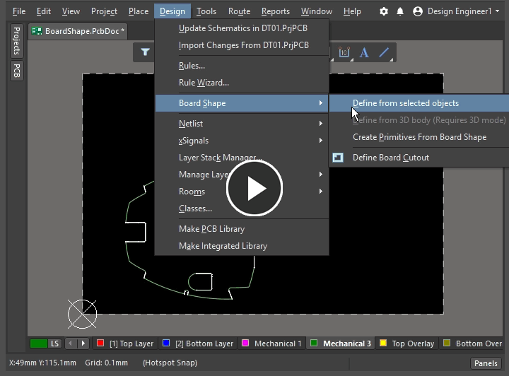
- Run the Design » Board Shape » Define from selected objects command - the board shape will be redefined to the selected objects and the display updated.
- Open the View Configuration panel and double-click to edit the mechanical layer that holds the board shape. The Edit Layer dialog will open, where you can set the Layer Type to
Board, as shown in the animation below.
Defining the Board Shape from a 3D Body
This feature redefines the board shape based on a surface (face) of an imported 3D STEP model. It can be used to quickly create a complex board shape and helps integration between electronic and mechanical design areas. This is a two-stage process: first the STEP model is imported, then the required shape is selected from the STEP model.
To do this:
- Switch to View » 3D Layout Mode.
- To import the STEP model (.step or .stp) place a 3D body (Place » 3D Body), then in the 3D Body mode of the Properties panel, select Generic in the 3D Model Type region. Select Embed Model or Link to Model in the Source region to import the required STEP model. Note that this STEP model can be deleted once the board shape has been redefined.
- Select Design » Board Shape » Define from 3D body.
- The Status bar will prompt you to Pick a 3D body. Click the imported 3D body to select it.
- The cursor will change to a crosshair and the Status bar will prompt you to Choose Face. As you hover the cursor over each face, it will be outlined. Click to select the correct face.
- The Board Outline Creation Successful dialog will appear, displaying options on how you want the imported 3D model positioned in relation to the newly-defined board shape. These can be ignored if you are planning on deleting the STEP model, otherwise configure the options as required.
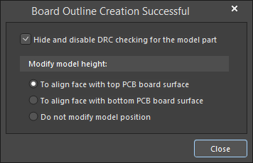
Note that if you keep the STEP model embedded in or linked to the PCB file, you will be notified whenever the STEP file changes. You will also be prompted to update the shape, which is a handy feature if the shape is still under development and updates are expected.
Modifying or Redefining the Board Shape
In Board Planning Mode you can modify the board shape by moving the vertices or completely redraw (redefine) it. Refer to the Board Shape object to learn more.
Redefining the Board Shape Using Jump Location
To accurately define the shape based on a set of dimensions, you can use the Jump Location shortcut keys instead of the mouse. To do this:
- Set the origin to define the location of the bottom left of the PCB (Edit » Origin » Set).
- Switch the workspace to Board Planning Mode (View » Board Planning Mode).
- Select Design » Redefine Board Shape and release the mouse.
- Press the J key to open the Jump submenu.
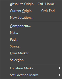
Press the O key to jump to the origin you just defined. Press Enter to define the first corner of the new board shape.
- Press J, L to open the Jump to Location dialog.
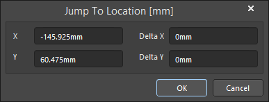
The X-Location field will be active; type in the X location of the next corner of the board (do not touch the mouse).
- Press the Tab key to move to the Y-Location field in the Jump to Location dialog then type in the appropriate Y value.
- Press Enter to accept the values and close the dialog. The cursor will be at the correct location. Do not touch the mouse; press the Enter key again to define this corner.
- Press J, L again to open the Jump to Location dialog. Type in the next X coordinate, press Tab, type in the Y coordinate, press Enter to accept the values then press ENTER to define this corner.
- Repeat this process until all corners are defined, finishing back at the 0, 0 origin. Again, do not touch the mouse; press Enter.
Interactively Editing the Board Shape
The board shape is a polygonal object, another approach is to set the grid (Ctrl+G) to a relatively coarse value and interactively modify the shape, as demonstrated in the animation below .
 If the board is rectangular it can be quicker to set a coarse grid and interactively modify the shape.
► Learn more about modifying a polygonal object.