
编辑多边形PCB设计对象
- Region - Region objects are used to create polygonal-shaped copper regions, polygon cutouts, board cutouts, and cavity definitions.
- Polygon - Polygons can be created from region objects or tracks and arcs. When created from regions, each isolated section of copper is a region object.
- Extruded 3D Body - The plan view of an extruded 3D Body is defined as a polygonal shape.
- Board Shape - A board shape or board outline is a closed polygon that defines the boundary, or extents, of the board.
- Room - A room is a primitive design object. It is a region that assists in the placement of components.
Editing a Polygonal Object
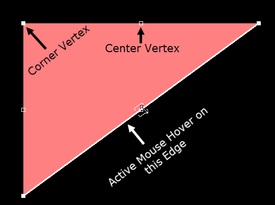
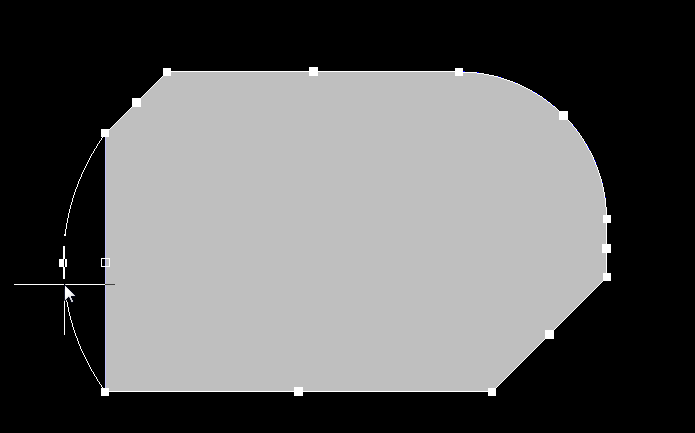
Click once on a polygonal object to select it, which puts the polygonal object into edit mode. The outer shape of the polygonal object is defined by a series of edges. Each edge is represented by an end vertex at each end, shown as a solid white square, and a center vertex in the middle, shown as a hollow white square. Each end vertex represents the location where two edges meet.
Combining Selected Polygon Pours
Two or more polygon pour objects can be combined by performing the following sequence of actions:
- Place new (or drag existing polygon pours) so that they are overlapping each other as required.
- Select all polygon pours that are to be combined.
- Right-click over one of the pours in the selection then choose the Polygon Actions » Combine Selected Polygons command from the context menu.

Combining two existing polygon pours to make a single polygon pour.
Subtracting Selected Polygon Pours
One or more polygon pour objects can be subtracted from another 'base' polygon pour by performing the following sequence of actions:
- Place new, or drag existing polygon pours so that they are overlapping the required base polygon pour - this is the pour from which to be 'subtracted'.
- Select the base polygon pour, right-click then choose the Polygon Actions » Subtract Polygons From Selected command from the context menu.
- Select the polygons to be subtracted.
- Right-click or press Esc to complete the process.

Subtracting an existing polygon pour from an existing 'base' polygon pour.
Modify Polygon Border
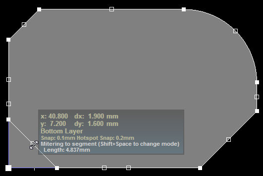
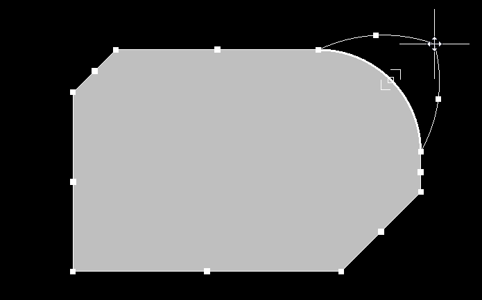
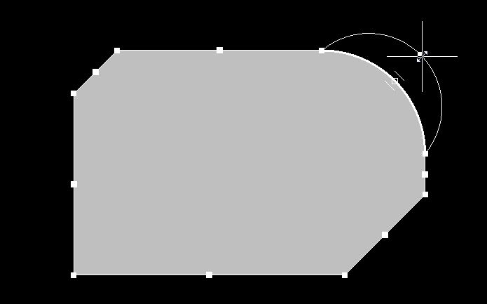
In addition to the vertex editing, the Modify Polygon Border command allows you to easily change the shape of polygons. The command is performed by right-clicking on the desired polygon then selecting Polygon Actions » Modify Polygon Border. Once the command is launched, the cursor becomes a crosshair. Each time you click, a new vertex is added. As during polygon placement, the Shift+Spacebar keys can be used to change corner shapes.
 Modifying a polygon border.
Modify Board Shape
Similarly to the Modify Polygon Border command, the Modify Board Shape command allows you to easily change the shape of the board. The command is accessed in Board Planning Mode (View » Board Planning Mode) by clicking Design » Modify Board Shape. Once the command is launched, the cursor becomes a crosshair. Each time you click, a new vertex is added. The Shift+Spacebar keys can be used to change corner shapes.
Modify Region Border
In addition to the vertex editing, the Modify Region Border command allows you to easily change the shape of polygons. The command is run by right-clicking on the desired region then selecting Polygon Actions » Modify Polygon Border. Once the command is launched, the cursor becomes a crosshair. Each time you click, a new vertex is added. The Shift+Spacebar keys can be used to change corner shapes.
Vertex Editing Modes
When editing polygons, there are three editing modes available: Miter, Incurvate (arc) and Move. The current mode can be changed while dragging a vertex by pressing the Shift+Spacebar keys to cycle through the modes. Feedback about where the cursor is on the board and which editing mode is currently active can be viewed on the Status bar and in the Heads-Up display.
Break Mode
In this mode, click and drag on the center vertex to break that edge into two edges. The cursor displays a double-arrow indicating the Break mode. Note that the mouse cursor has four arrow heads that indicate that you can drag this vertex in all four directions.

 Breaking an arc into two arcs.

 Breaking a straight edge into two straight edges.
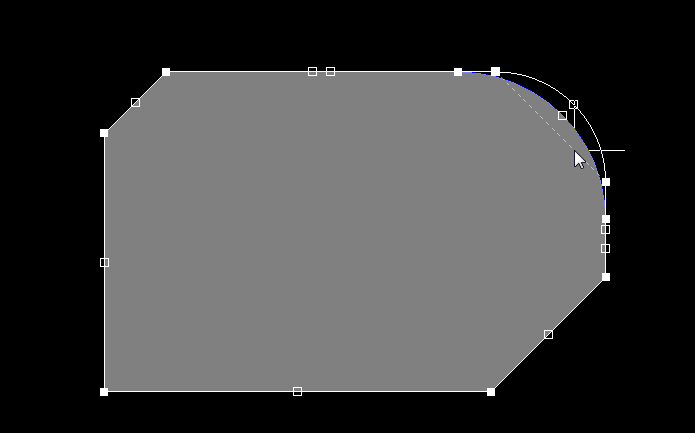
Incurvate (Arc) Mode
In this mode, click and drag on the center vertex to incurvate, or arc, that edge. Note that the mouse cursor has two arrow heads indicating that you can drag this vertex in two directions.

Arcing an arc edge into a larger or smaller arc.

Arcing a straight edge.
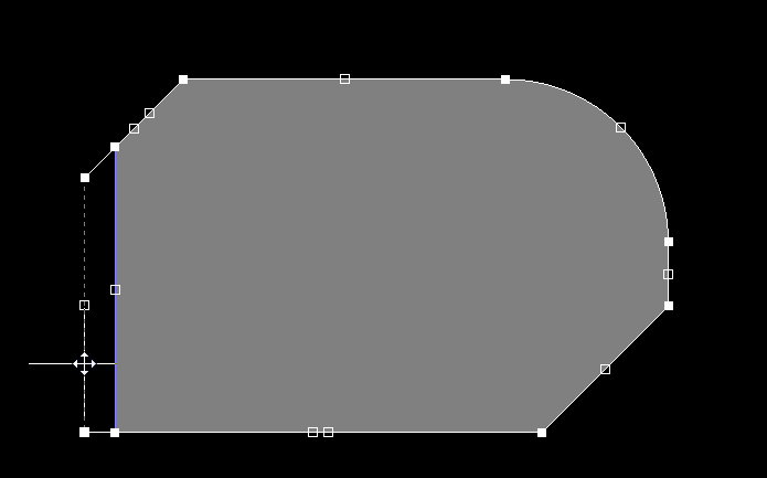
Move Mode
In this mode, click and drag on the center vertex to move that edge, maintaining the edge length. Note that the mouse cursor has four arrow heads, indicating that you can drag this vertex in all four directions.

Moving an arc while maintaining its length.

Moving a straight edge while maintaining its length.
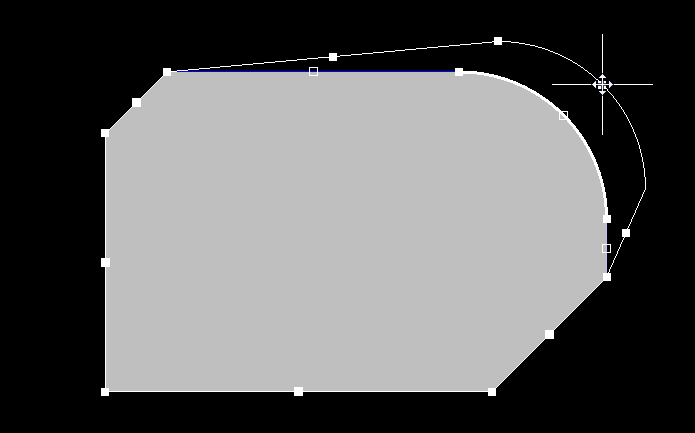
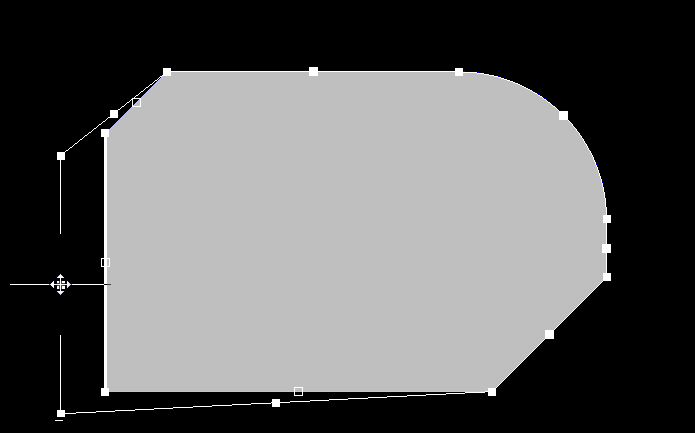
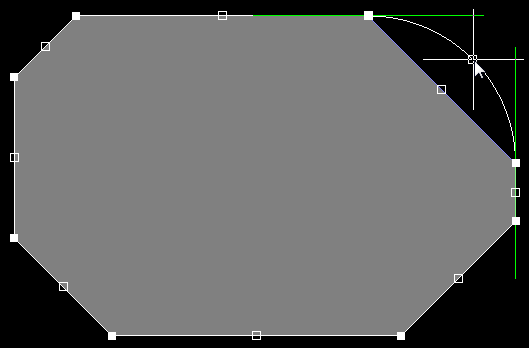
Corner Vertex Behavior
The three editing modes are also available when moving a corner vertex.


The first image shows the mouse hovering over the corner vertex; the second image shows the vertex moving in Moving Vertex mode.

The first image shows the vertex moving in Mitering to Arc mode; the second image shows the vertex moving in Mitering to Segment mode.
Sliding an Edge
When you hover over an edge, that edge displays as a thick white line. Click+drag on the edge to slide it, shrink or grow the moving edge to maintain the position of adjoining edges.
Sliding the arc edge while maintaining the size and position of adjoining edges.

Sliding the straight edge while maintaining the size and position of adjoining edges.
Adding or Deleting a Vertex
You can interactively add a vertex or delete a vertex using the following techniques:
- To add a vertex, hold Ctrl then position the cursor along the edge — the new vertex displays under the cursor — click and move the cursor slightly to insert the new vertex.
- To delete a vertex, click and hold on the vertex as if you were going to move it, then press the Delete key.
, or click & hold on an existing vertex and use the Delete key to remove that vertex (second image).")

Ctrl, hover, then click to add a vertex (first image), or click & hold on an existing vertex and use the Delete key to remove that vertex (second image).
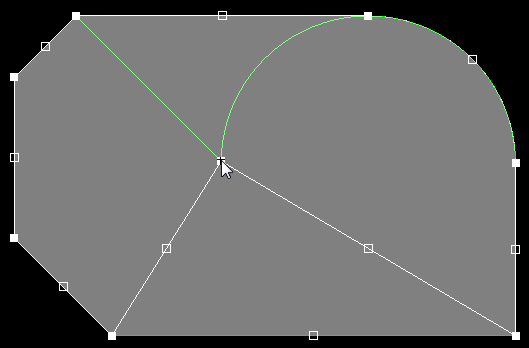
Alignment Guides
As you move a vertex around, green alignment guides appear. These appear at useful locations, for example, when the vertex location will result in the new edge aligning with an existing edge or when an arc chord aligns with the adjacent edge. There is a slight stickiness when the guidelines appear, making it easy to maintain that vertex position.
. Second image - using the guidelines to align a new arc to existing edges.")
First image - using the guideline to remove an arc (incurvate mode). Second image - using the guidelines to align a new arc to existing edges.

First image - using the guidelines to help align the breaking edge with existing edges. Second image - using the guidelines to align the new vertex location to existing vertices.