同步软硬结合线路板
Parent page: ECAD-MCAD CoDesign
Perhaps the most challenging printed circuit board design to bring to production is a rigid-flex design. Designing a flex or rigid-flex circuit is very much an electromechanical process. Designing any PCB is a three-dimensional design process, but for a flex or rigid-flex design, the three-dimensional requirements are much more important. Why? Because the rigid-flex board may attach to multiple surfaces within the product enclosure during the product assembly process, requiring careful design of how the loaded board must flex during assembly to interface to the enclosure.
To date, this tight electro-mechanical design challenge has been solved by making a mechanical mock-up, also known as a paper doll cut-out. This process must be as accurate and realistic as possible with all possible mechanical and hardware elements included so that both the assembly process and the finished assembly can be carefully analyzed.
Altium CoDesign helps solve this challenge, delivering the ability to transfer the rigid-flex design between the ECAD and MCAD domains. It does this by implementing each flex region of the board as an MCAD Sheet-Metal Feature.
Rigid-Flex Design in ECAD
In Altium's PCB editor, the rigid-flex board is designed in the X-Y plane as a collection of separate rigid and flexible board regions. The Z-plane is defined by configuring the set of copper, insulation, and surface finishing layers to be created during the board fabrication process.
For a rigid-flex design, the set of fabrication layers can be different for each region of the board. For example, one rigid region might be four copper layers, a flex region projecting from that rigid region might be one copper and one melamine layer, and the flex region might connect to another rigid region, made up of six copper layers. During ECAD PCB design, a separate layerstack is defined and assigned to each of these regions.
 A board with two rigid regions connected by a flexible region in the ECAD PCB editor, and in MCAD.
In Altium's design software the rigid-flex board is designed flat. Bends defined in the flex regions can be applied when the board is displayed in the PCB editor's 3D Layout Mode, by sliding the Fold State slider in the Layer Stack Regions mode of the PCB panel. The bends are applied in the Sequence order configured in the panel. Alternatively, use the 5 shortcut key in the ECAD PCB editor to fold and unfold the board.
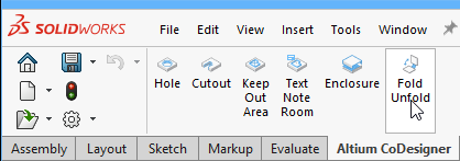
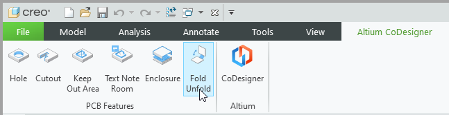
The board is Pushed to MCAD in the folded state, the bends can then be suppressed in MCAD to display and work on the board. To Fold or Unfold the board in MCAD, click the Fold Unfold button on the Altium CoDesigner ribbon (show image).
► Learn more about Defining the Layer Stack
► Learn more about Defining Board Regions and Bending Lines
► Learn more about Rigid-Flex Design
Requirements for the ECAD Board Definition
When the board is Pushed from ECAD, CoDesigner checks for potential issues with the board outline, and the location and size of bending areas. On Pull in to MCAD, CoDesigner also checks the radius of each bend and rejects any bend that cannot be rendered as an MCAD sheet metal bend.
The Board Shape
On Push from ECAD, the board contour (outline) is tested. If there are micro-segments or self-intersecting contours detected, they must be resolved. CoDesigner 2.4 introduced an automatic feature to detect and resolve micro-segments in the board outline.
 CoDesigner tests the board outline for issues that cannot be supported in MCAD and will resolve them automatically.
If you choose not to resolve the micro-segments automatically, or there are self-intersecting contours in the outline, or micro-segments or self-intersecting contours in a board cutout, these must be resolved manually. Learn more about Resolving Issues with the Board Contour
Bending Lines
In ECAD, technically there is no limit to the properties that can be applied to a bend in a flexible PCB. In MCAD, sheet-metal capabilities are used to represent the flexible segments of the board. To ensure that the bends can be represented in MCAD, the following requirements must be met:
- A bending area should not overlap or touch another bending area or rigid region. The bend radius must not extend beyond an adjacent split line, requiring at least 0.5 mil (0.0127 mm) distance between the edge of the bend area and a rigid region. This is tested when you Push in ECAD, any issues detected must be resolved to be able to Push successfully.
.") In this design, the bend area is too close to the split line (less than 0.5mil).
In this design, the bend area is too close to the split line (less than 0.5mil).
- Suitable bending radii are defined. CoDesigner checks for: a bending radius that is too small; a bending angle that is too big; or bending segments that are too short. This is checked during Pull in to MCAD, taking the thickness of “metal” and the bend relief requirements into consideration.
 Two bends have a radius that is too small to be formed in sheet metal, so they cannot be created.
Advanced Rigid-Flex Design
Switch to the Advanced Rigid-Flex mode in the ECAD PCB Editor if your design requires any of the following ECAD-MCAD rigid-flex features:
- Flex regions with different thicknesses
- Separate flexible regions that overlap each other
- Representation of copper and silkscreen on the rigid regions in MCAD in SOLIDWORKS
- A local bend (a bend that is localized to a flex region that is within a cutout in a larger flex region)
 An Advanced Rigid-Flex design with overlapping flex regions of different thicknesses, open in Altium Designer and in PTC Creo.
Summary of the Structure of an Advanced Rigid-Flex (RF2) Board in MCAD
Below is a summary of the MCAD structure of an Advanced Rigid-Flex board:
- Each rigid region of an RF2 design is represented as an MCAD Assembly, which includes that rigid part (region) of the board, and components mounted on that region (very similar to how a rigid PCB is modeled in MCAD).
- Each flex region of the board is represented as a sheet metal part. Within this part, each ECAD Bend Line is defined as a Sketched Bend. Note that a bend that can be Pushed from ECAD might not be formed correctly in MCAD, due to the bend requirements of that MCAD tool. Also, note that components on flex regions are not yet supported.
- For cutouts that extend through multiple board regions, separate cut extrudes are created in MCAD. If the mechanical engineer wants to change the shape of such a cutout in MCAD, they must change all of those extrudes.
The following videos provide an overview of how CoDesigner constructs an Advanced Rigid-Flex board in MCAD (which differs from how a standard Rigid-Flex board is constructed). While it is demonstrated in SOLIDWORKS, the flow is essentially the same in PTC Creo, differences are noted in the video captions.
Video 1 – Advanced Rigid-Flex, Understanding the Structure
Overview of how CoDesigner constructs a board in MCAD.
Video 2 – Advanced Rigid-Flex, Modifying the Board Regions
Modifying the rigid-flex board shape in MCAD.
Video 3 – Advanced Rigid-Flex, Modifying the Bends
Modifying and adding bends to a rigid-flex board in MCAD.
Notes on Working with Advanced Rigid Flex Boards
- For an RF2 board in ECAD, each X-Y region of the board is drawn as a separate object, which then has a substack assigned to it (whereas in an RF1 board you define the overall board shape, and then place Split lines to divide it into the required board regions). Gaps between adjacent regions in an RF2 are not permitted, they must exactly touch or overlap. If two regions overlap, the software assumes that the shared zone belongs to the region with the greater number of layers. Using this knowledge, extending a flexible region into the adjacent rigid region can be easier if it is difficult to align their edges. Learn more about Planning Rigid & Flex Regions - Advanced Mode.
- The ECAD PCB editor includes several tools to help create regions from existing line/arc objects, learn more about Creating Board Regions from Selected Objects.
- In ECAD, each unique set of layers (substack) must be defined, either by copying existing layers to create the new substack, or by adding layers to define a unique substack. Learn more about Adding and Editing a New Substack.
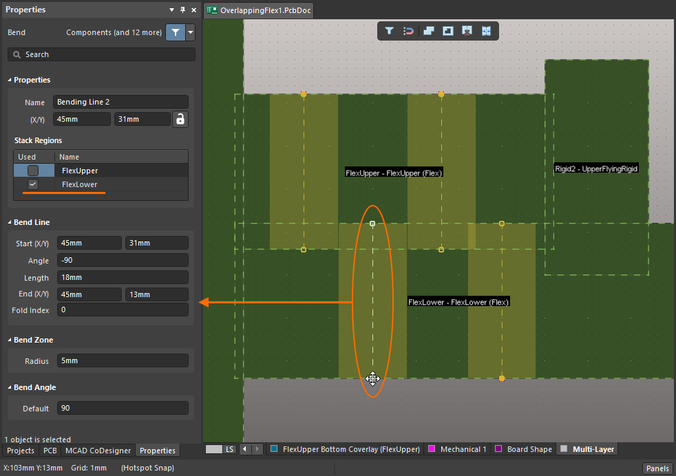
- RF2 mode supports flexible regions that overlap each other in 3-dimensional space. To support this, when a Bend Line is placed in Board Planning Mode in ECAD the designer must ensure that the Bend is applied to the correct flexible Stack Region (show image). If this is not done, an unaffected region warning will be displayed when the design is Pushed from ECAD to MCAD (show image).
- The structure of the PCB assembly in RF2 mode in SOLIDWORKS differs from the structure of the assembly in RF1 mode in SOLIDWORKS, so if the mode is switched from RF1 to RF2 in ECAD, it's recommended to do a fresh Pull of the board in SOLIDWORKS. In Creo, the structure of the PCB assembly is unified for both RF1 and RF2, so you will not see any change in the MCAD feature tree.
- The decals representing the top/bottom copper, silkscreen, and soldermask are now applied to the rigid regions in RF2 mode in SOLIDWORKS.
- When editing the geometry of the PCB in MCAD, keep in mind that there is no associativity between the geometry of the neighboring regions. If the geometry of one region is modified, adjust the geometry of the neighboring region to suit.
- If you make significant changes to the geometry, for example, changing the set of edges, the constraints in MCAD may be broken. This is normal, they will be restored on the next MCAD-ECAD-MCAD synchronization.
- After making changes to bends, an MCAD Rebuild operation will be required in most cases.
- If your designs are stored in Altium 365, the automatic push that happens after you Save the project to the server will not process your rigid-flex board changes (the RF2 changes have not been added to the ECAD server-side automatic push yet). After saving a rigid-flex project to the server, you must also manually Push your PCB to MCAD in the MCAD CoDesigner panel.
- Building 3D copper and specifying the enclosure in the PCB definition in MCAD (and sending the enclosure to ECAD), are not currently supported for rigid-flex boards.
-
The flexible regions of your PCB design are modeled in MCAD as sheet metal. Each MCAD tool has its own set of tests that it applies to verify that a bend can be formed in the sheet metal, taking into consideration the:
- Board thickness
- Bend Radius
- Bending angle
- Distance between bending area and region border

Rigid-Flex Design in SOLIDWORKS
MCAD CoDesigner in SOLIDWORKS supports Pulling and Pushing a Rigid-Flex PCB that has been designed in either the Standard Rigid-Flex mode (RF1), or the Advanced Rigid-Flex mode (RF2).
Board Structure in SOLIDWORKS
When the rigid-flex board is Pulled into SOLIDWORKS, the board structure is mapped in the following way:
| Standard Rigid-Flex (RF1) | Advanced Rigid-Flex (RF2) |
|---|---|
|
|
|
|
|
|
|
|
|
|
|
|
|
|
SOLIDWORKS Capability Support
| Feature | Standard Rigid-Flex (RF1) | Advanced Rigid-Flex (RF2) |
|---|---|---|
| The transfer of rigid-flex boards from ECAD to MCAD and back | Supported | Supported |
| Preview the ECAD changes in MCAD | Supported | Supported |
| Create new rigid and flex board regions in MCAD | Supported | Not yet supported * |
| Create new bends in MCAD | Supported | Not yet supported * |
| Make changes to the geometry of the rigid and flex segments of the board. For example, adjust the board’s shape to suit the geometry of the product enclosure, create cutouts or mounting holes, or change the radius of a bend. | Supported | Supported |
| Transfer boards that include flex regions that have different thicknesses | Not available in RF1 | Supported |
| Transfer copper and silkscreen detail on rigid regions ^ | Not supported | Supported |
| Make changes to the placement of existing components, and place new components on the board. | Supported | Supported |
| Push placement changes to ECAD and pull new changes from ECAD | Supported | Supported |
| Create a rigid-flex board from scratch in MCAD | Not yet supported | Not yet supported |
| Transfer components mounted on a flex region from ECAD to MCAD | Not yet supported | Not yet supported |
| Place components on a flex region in MCAD | Not yet supported | Not yet supported |
| Create new board regions on a flex-only board | Not yet supported | Not yet supported |
Working with a Rigid-Flex Board in SOLIDWORKS
In SOLIDWORKS, a rigid-flex board is Pulled from your Server like a standard rigid board. If you are not currently signed in to your Server, refer to the topic Installing and Configuring CoDesigner in Your MCAD Software.
Changing the board shape in MCAD
- To change the shape of a board region
- Open (expand) the main board Part in the model tree.
- Open the first flex Region Feature and start editing its Sketch (this is the master Sketch for the entire board).
- Each edge will include an anchor, these are added by CoDesigner during initial creation for internal purposes, they can be deleted as required to modify the Sketch.
- The lines that split the board regions can be deleted and recreated if required.
- Modify the shape as required.
 Edit the master Sketch to change the shape of the board.
- To create or redefine a flex region
If a split line has been removed and redrawn, the flex region will need to be redefined.- Edit the flex feature in the model tree.
- Check that the correct Contour in the Sketch is being used for the flex region. If it is not, delete the Selected Contour and select the correct one.
- Make sure that the extrude feature that represents the flex region has the correct thickness and correct offset from the bottom and/or top board face.
- Bends in this flex region may have also been broken, there are tips for fixing these below.
- To add new sketched bends, or change or remove existing ones
- Select a Sketched Bend and Edit it to change its location, angle or radius.
- At least one bend that came from ECAD should be kept alive – CoDesigner uses a bend as a reference when the board is pushed back from MCAD to ECAD.
- If you are modifying the shape of a board that has components placed, your MCAD software may re-assign the internal IDs to the faces/vertices, which can result in breaking the coordinate systems used for the attachment of the components to the board. For this reason, if you are going to make significant changes to the board shape in MCAD, it is better to do that without the components having been placed.
- If the components have been placed: create the bends in ECAD as close to their final position as possible, and then only adjust the bend(s) in MCAD. Alternatively, if your MCAD software breaks the coordinate system, you can restore the definition of the coordinate systems manually. Or you can simply ignore the changes made to the component placement when pulling the changed board back into ECAD.
- To create a cutout or a mounting hole
- Start editing the main board Part.
- To ensure the Cut Extrude or Hole is created before the board is flexed, move the “feature visibility” bar of the Cut Extrude or Hole upward in the model tree and place it above the first Bend feature.
- Create a Cut Extrude or Hole on the board part (with the sketch located on its top or bottom face).
- Move the “feature visibility” bar back to the bottom of the tree.
Making Changes to Component Placement in MCAD
- To define the precise location of a component (universal approach)
- Move your component upwards in the model tree to the board assembly level (if you want to locate that component relative to the board) or to the device level (if you want to locate that component relative to the enclosure).
- Define the precise location of that component using mates or dimensions. Then delete those mates/dimensions.
- Move your component back into the initial component subassembly (or to another subassembly if required) in the model tree.
- To make a simple movement/rotation of a component on the same board face within one rigid region
- Start editing the corresponding component subassembly.
- Move/rotate the component using the corresponding capabilities of your MCAD software.
Additional Recommendations for the Mechanical Engineer
- To unfold/fold all bends on a board (for example, to check for overlapping)
- Click the Fold Unfold button on the Altium CoDesigner ribbon.
- To selectively unfold/fold a bend (or bends)
- Open (expand) the main board part (RF1) or the FlexPart (RF2) in the model tree.
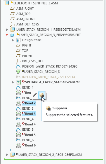
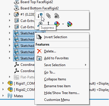
- Select the Sketched Bend feature(s) in the model tree, right-click and Suppress them (show image).
- Unsuppress the Bend feature(s) to restore the bend(s) and re-fold the board.
- After unfolding/re-folding a board, it is recommended to Rebuild the model (Ctrl+B in SOLIDWORKS).
- If you break a model (and rebuild or undo does not help)
- If your latest changes were not saved, simply close your PCB assembly without saving, and open it again.
- If saved, pull changes from your managed content server and apply only those that are related to the broken entities.
- If pulling changes did not help, close your PCB assembly and do a fresh pull to overwrite the original PCB assembly (keep in mind that the changes you just made to the PCB will be lost).
- Other recommendations
- Do not change the set of existing coordinate systems and the set of mates between them. (there is a big chance that you will break the model)
Rigid-Flex Design in PTC Creo
MCAD CoDesigner in PTC Creo supports Pulling and Pushing a Rigid-Flex PCB that has been designed in either the Standard Rigid-Flex mode (RF1), or the Advanced Rigid-Flex mode (RF2).
Board Structure in PTC Creo (RF1 and RF2)
When the rigid-flex board is Pulled into PTC Creo, the board structure is mapped in the following way:
- A Creo assembly is created for the entire board, named
<PcbProjectName>. - A Creo assembly is created for the flex part of the board, named
BOARD_<PcbProjectName><CoD_UID>.- Within this assembly, a Creo Sheetmetal part is created.
- For each bend in a flex region, a Creo Sketched Bend is created. Sketched Bends can be suppressed in Creo to flatten the board out.
- A coordinate system is defined at one end of each of the rigid-flex split lines. Each of these coordinate systems is used for mating each rigid region component assembly (described below).
- The board outline is defined by a Sketch. This Master Sketch includes all regions.
- A Creo Assembly is created for each rigid region of the board, named
<PcbRegionName>_<CoD_UID>. The assembly includes a Creo Part that represents the rigid region itself, and a Creo Part that represents each component mounted on that region. This assembly is mated to the board part by a local coordinate system.
Creo Capability Support
| Feature | Standard Rigid-Flex (RF1) | Advanced Rigid-Flex (RF2) |
|---|---|---|
| The transfer of rigid-flex boards from ECAD to MCAD and back | Supported | Supported |
| Preview the ECAD changes in MCAD | Supported | Supported |
| Create new rigid and flex board regions in MCAD | Not yet supported | Not yet supported |
| Create new bends in MCAD | Not yet supported | Not yet supported |
| Make changes to the geometry of the rigid and flex segments of the board. For example, adjust the board’s shape to suit the geometry of the product enclosure, create cutouts or mounting holes, or change the radius of a bend. | Supported | Supported |
| Transfer boards that include flex regions that have different thicknesses | Not available in RF1 | Supported |
| Transfer copper and silkscreen detail on rigid regions ^ | Supported | Supported |
| Make changes to the placement of existing components, and place new components on the board. | Supported | Supported |
| Push placement changes to ECAD and pull new changes from ECAD | Supported | Supported |
| Create a rigid-flex board from scratch in MCAD | Not yet supported | Not yet supported |
| Transfer components mounted on a flex region from ECAD to MCAD | Not yet supported | Not yet supported |
| Place components on a flex region in MCAD | Not yet supported | Not yet supported |
| Create new board regions on a flex-only board | Not yet supported | Not yet supported |
Working with a Rigid-Flex Board in Creo
Changing the board shape in MCAD
- To change the shape of a board region
- Start editing the Flex Part.
- Modify the shape of any segment of that part as required.
- Keep the integrity of the flex part: The segments should not overlap each other, and there should not be gaps between them.
- Stop editing the Flex Part.
- (Optional) Start editing the rigid parts that correspond to the segments you changed. Make the corresponding changes to them.
- To create a cutout or a mounting hole
- Start editing the Flex Part.
- Suppress the bend features to unfold the Flex part.
- Create a Hole or an Extruded Cut on the flex part (with the sketch located on its top or bottom face).
- Move it in the model tree so that it’s located before bends.
- (Optional) Start editing the rigid parts that correspond to the segments you changed. Make the corresponding changes to them.
- Go back to the flex part and Resume the bends. After unfolding/re-folding a board, it is recommended to Regenerate the model (Ctrl+G in Creo).
Additional Recommendations for the Mechanical Engineer
- To unfold/fold all bends on a board (for example, to check for overlapping)
- Click the Fold Unfold button on the Altium CoDesigner ribbon.
- To selectively unfold/fold a bend (or bends)
- Open (expand) the main board part (RF1) or the FlexPart (RF2) in the model tree.
- Select the Sketched Bend feature(s) in the model tree, and Suppress them (show image).
- Resume the Bend feature(s) to restore the bend(s) and re-fold the board.
- After unfolding/re-folding a board, it is recommended to Regenerate the model (Ctrl+G in Creo).
- If you break a model (and rebuild or undo does not help)
- If your latest changes were not saved, simply close your PCB assembly without saving, and open it again.
- If saved, pull changes from your managed content server and apply only those that are related to the broken entities.