
Working with a Via Type View Object on a Draftsman Document in Altium Designer
This document is no longer available beyond version 22. Information can now be found here: Via Type View for version 24
Parent page: Draftsman Design Objects
.")
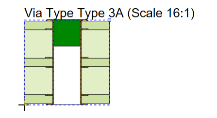
A placed Via Type View used to illustrate a Type 3A via (sealing with a non-conductive material on one side, which partially enters the via).
Summary
The Draftsman Via Type View feature allows a via type (according to the IPC-4761 standard, Design Guide for Protection of Printed Board Via Structures) to be placed as an independent single drawing view object. The display style and content of a Via Type View is configurable in the Properties panel.
A Callout placed on the Via Type View will automatically identify the associated via structure.
Availability
Via Type Views are available for placement in a PCB project Draftsman document from the Draftsman Editor as follows:
- Choose the Place » Additional Views » Via Type View command from the main menus.
-
Click the Via Type View option (
 ) in the view objects drop-down on the Active Bar located at the top of the design space. Click and hold an Active Bar button to access other related commands. Once a command has been used, it will become the topmost item on that section of the Active Bar.
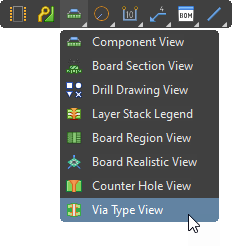
- Right-click in the drawing design space then select Place » Additional Views » Via Type View from the context menu.
- Click the
 entry on the Drawing Views toolbar (View » Toolbars » Drawing Views to enable).
Placement
After launching the command, the cursor will change to a cross-hair and the rendered Via Type View is attached to the cursor. Move the cursor to the desired position then click to confirm the placement.
A default via type is initially shown, however, the view selection can be changed in the Properties panel to specify any available via type.
Graphical Editing
Both the position and size of placed Via Type View may be graphically modified.
- A selected Via Type View will show a node handle at the top right of the selection outline, which can be dragged to modify the view's size.
- To move a Via Type View, click within the selection then drag and drop it to a new location.
- As a Via Type View is being dragged, press the Spacebar to rotate the object in 90° increments.
Non-Graphical Editing
Properties page: Via Type View Properties
The non-graphical method of editing a Via Type View is available in the Draftsman Properties panel, which provides a comprehensive range of editable properties, options and design content settings for placed Draftsman objects that are currently selected in the design space.

The Properties panel when a Via Type View is selected.
To open the Properties panel and access the properties of a placed Via Type View:
- After selecting the Via Type View object, select the Properties panel from the Panels button at the bottom right of the design space or select View » Panels » Properties from the main menus.
- Double-click on the Via Type View object in the design space.
- Right-click on the Via Type View then select Item Properties from the context menu.
If the Properties panel is already active, click on the Via Type View object to access its properties in the panel.
Editing Multiple Objects
The Properties panel supports multiple object editing, where the property settings that are identical in all currently selected objects can be modified.