
PCBLIB过滤器面板
This document is no longer available beyond version 4. Information can now be found here: PCBLIB Filter Panel for version 5
Parent page: Working with Panels
Summary
The PCBLIB Filter panel provides controls to construct filters through the creation of logical queries. A defined filter can then be applied to the active PCB component footprint, or all component footprints in the active PCB library, allowing you to select and edit multiple objects with great accuracy and efficiency.
Panel Access
The panel is accessed from the PCB Library Editor in the following ways:
- Click the Panels button at the bottom-right of the workspace then select the PCBLIB Filter entry.
- Click View » Panels » PCBLIB Filter from the main menus.
- Use the F12 shortcut key.
Panel Sections
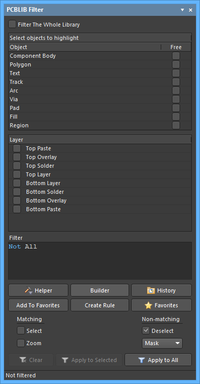
The PCBLIB Filter panel is composed of three regions. The first two are selectable list areas that collectively define the scope of the filtering: Object and Layer. The third region, Filter, displays the query created based on the objects and layers that are currently selected.
Building Simple Filter Expressions
The main region of the panel provides controls for quickly building simple filter expressions targeting any combination of objects. Object types are arranged in an 'object matrix', categorized in accordance with being net objects (Net), component objects (Comp), or free objects (Free). The following core object list is replicated across these three groups:
- Track
- Arc
- Via
- Pad
- Fill
- Region
The Text object is available as part of the Comp and Free groupings, however, since this object type is not net-aware, it is not part of the Net grouping. In addition, the Free grouping also includes Component, ComponentBody, Room, and Polygon.
If these are set to 'Components' and 'Top Layer', for example, the board view will highlight top layer components. The selections in both panel sections represent the cumulative effect of multiple stages of filtering action, which can be used to quickly highlight any type of design object.
To use an object in the construction of a filter expression, i.e. filtering by that object, enable the relevant check box associated with that object within the object matrix. Commands available on the right-click context menu for the region enable you to quickly check or uncheck all entries in the matrix, or toggle the state of all checkboxes in the matrix, respectively.
Use the Layer region to restrict the filter to a particular layer or layers or a specific class of layers. The entries listed reflect:
- The defined layer classes for the board, the default of which are:
- <All Layers>
- <Component Layers>
- <Electrical Layers>
- <Signal Layers>
- The defined layers in the layer stack (as presented in the Layer Stack).
- The top and bottom paste mask layers.
As you make your filtering selections, the resulting query expression is built dynamically and presented in the Filter region of the panel. Once the filter query expression has been defined as required, you then need to apply it as a separate action. To do this, click the Apply to All button at the bottom of the panel. Alternatively, if you require application to only those objects that are currently selected in the workspace, use the Apply to Selected button.
Applying Filtering
PCB Library components are composed of primitive object types (Arcs, Pads, Tracks, etc.,) arranged on different board Layers. The objects are either 'free' in nature or 'owned' by a group object. Note that selecting Free in the Object region will highlight only those objects that are not part of a group object.
Filtering by Object
The selection in the panel's Object list will filter the board view to show primitive design objects. All objects will be highlighted unless modified by the settings in the Layer filter list.
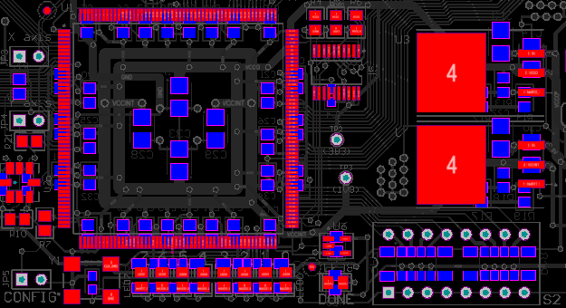
The example board shown with Track and Arc selected under Object.
Layer is set to Top Overlay.
Filtering by Layer
The selection in the panel's Layers list will filter the board view to show objects on the nominated physical design layer (Signal, Mask and Silkscreen layers). All valid Layer objects will be highlighted unless modified by the settings in the Object filter list.

The example board shown with Object set to Pad. Layer is set to Top Layer.
Selecting Filtered Objects
The collective filter action provided by the PCBLIB Filter panel assists both viewing and selecting board design objects of interest.
Only highlighted (filtered) objects are selectable, making it easy to locate, edit and find information about the object.
Clearing the Filter
Clear the currently applied filter with the panel's Clear button.
Setting the Visual Filtering
The visual result of the applied filtering on the document in the workspace is determined by a series of highlighting controls. The effect that is imposed in the editor view can be set to Normal, Mask or Dim, where in practice, Mask has the most obvious highlighting effect.
The Normal / Mask / Dim drop-down list provides options for visibly contrasting filtered and unfiltered objects within the workspace .

Select the type of visual filtering applied using the masking mode drop-down list.
The visual highlighting effect for each masking mode:
- Normal - filtered objects are visible in the workspace and the appearance of unfiltered objects remains unchanged.
- Mask - filtered objects are highlighted in the workspace with all other objects made monochrome.
- Dim - filtered objects are highlighted in the workspace with all other objects retaining their colors but shaded.
Defining Filter Queries
The central region of the panel allows you to construct filters through the entry of logical queries.
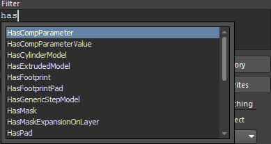
You can type a query directly into the field, and as you type, a prompt list of possible keywords will appear as an aid.
Two features are available to provide aid in the creation of queries - the Query Helper and the Query Builder. These facilities can be very useful if you are unsure of the syntax of a query or the possible keywords that you may want to use.
Query Helper
To use the Query Helper, click the Helper button to open the Query Helper dialog. The underlying Query Engine analyzes the document and lists all available objects, along with generic keywords for use in queries.
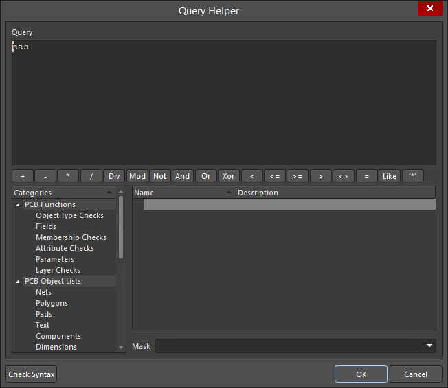
Use the top section of the dialog to compose a query expression using the available PCB Functions, PCB Object Lists, and System Functions. The middle region of the dialog provides a range of operators for use when constructing an expression. Use the Check Syntax button to verify that an expression is syntactically correct.
When the expression for the query has been defined as required, click OK to load the central region of the PCBLIB Filter panel with the query, ready to apply the filter.
Query Builder
To use the Query Builder, click the PCBLIB Filter panel's Builder button to open the Building Query from Board dialog.
This dialog enables you to create a query for targeting specific objects in the design document, by simple construction of a string of ANDed and/or ORed conditions.
The left side of the dialog is where you specify the condition(s) that are required to target the set of objects needed. Initially, the entry in the Condition Type/Operator column will be Add first condition. Click once on this entry to open a drop-down list of condition types.
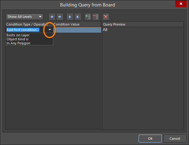
The condition types listed will only reflect those relevant to a board design.
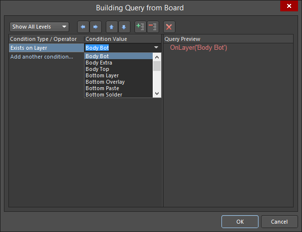
Select the condition then click in the Condition Value column to access a drop-down list of possible values for that condition type. As you define a condition in the left side of the dialog, a preview of the currently built query is shown on the right side.
Continue to add further conditions to narrow down the target set of design objects as required. Conditions can be ANDed or ORed together. The default logical operator is AND and is automatically inserted when you add another condition.
To change the logical operator between conditions, click on the AND or OR entry in the Condition Type/Operator column then select the required operator. The preview of the query will update accordingly.

Specifying Precedence
The  and
and  buttons at the top of the Building Query from Board dialog allow you to add and remove brackets around the presently selected condition (increasing and decreasing indent). This allows you to create precedence for certain logically ANDed or logically ORed conditions.
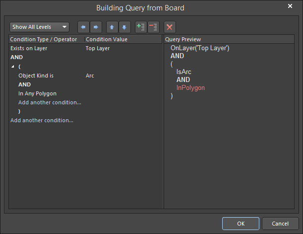
The first condition has been set to the condition type Exists on Layer with value Top Layer. Another condition has then been added using the condition type Object Kind is with the value Arc.

At this stage, with the second condition selected in the dialog, the right arrow button has been clicked. Brackets have been automatically added around the second condition, and now the possibility to add a condition within that pair of brackets is available.
![]()
The third condition with condition type In Any Polygon is then added within the brackets.
Use the Show All Levels drop-down at the top-left of the dialog to control the visual display of levels in your structured string of conditions. This essentially expands/collapses the display of brackets. Adding brackets effectively creates a new level. You can display levels 1-5, but for any further levels added use the Show All Levels option.
Alternatively, click on the expand or contract symbols associated with a bracketed condition to show the next level(s) or hide the current level (and all levels below) respectively. The  and
and  buttons at the top of the dialog also can be used to expand or collapse the currently selected condition.
Use the  and
and  buttons at the top of the dialog to move a selected condition in the query string being built. For a condition that has sub-levels (i.e. a bracketed condition), any condition in the level structure can be moved. When levels are expanded, a condition can be moved down or up through the levels. When levels are collapsed, a condition will be moved over the level structure.
To delete a condition, select it and either click the  button at the top of the dialog or use the Delete key.
When the expression for the query has been defined as required, click OK to load the central region of the PCBLIB Filter panel with the query, ready to apply the filter.
Historical Queries
As you enter and apply a new query, it will be added to a query history list. Click the History button in order to access this list - the dialog will open with the History tab active.
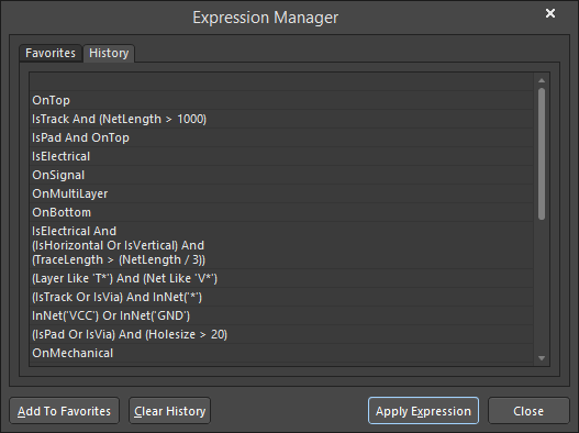
To use an historical query from the list, either select its entry then click on the Apply Expression button or double-click on the entry. The dialog will close and the expression for the query will be loaded into the central region of the PCBLIB Filter panel.
An historical query can be added to the list of favorite queries by selecting its entry and clicking the Add To Favorites button. Use the Clear History button if you want to 'flush' the history list. Up to nine of the most recently used query expressions from the list will be available for use from the panel's right-click menu.
Favorite Queries
Any defined query may be added to a list of favorite queries in two ways:
- Click the Add To Favorites command to add the query expression currently defined in the central region of the panel.
- Select an historical query entry in the History tab of the Expression Manager dialog then click the Add To Favorites button.
Click the Favorites button in the PCBLIB Filter panel in order to access this list. The Expression Manager dialog will open with the Favorites tab active.
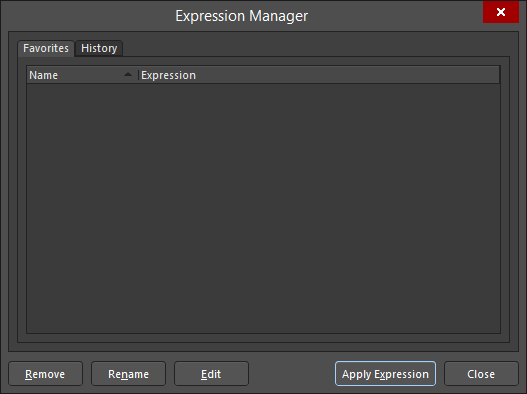
To use a favorite query from the list, either select its entry then click on the Apply Expression button or double-click on the entry. The dialog will close and the expression for the query will be loaded into the central region of the PCBLIB Filter panel.
When a query expression is added to the favorites list, it is assigned a unique name. By default, a generic name is assigned - Favorite_n - where n is the next available unused number. The name for an entry can be changed at any stage by using one of the following methods:
- Select the query entry then click the Rename button.
- Select the query entry then choose the Edit command from the available right-click menu.
- Select the query entry then click again within the Name field.
In each case, type the new name as required then click outside the Name field to effect the change.
To remove a query from the favorites list, select its entry in the list then either click on the Remove button or choose the Remove command from the right-click menu. A dialog will appear requesting confirmation of the removal. Up to 10 of the most recently added query expressions will be available for use from the top of the panel's right-click menu.
Creating Design Rules
The PCBLIB Filter panel also provides the facility for creating a design rule. Its scope will use the currently defined query expression in the central region of the panel.
To add a new design rule, click on the PCBLIB Filter panel's Create Rule button. The Choose Design Rule Type dialog will open.
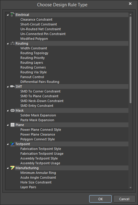
This dialog lists each of the rule categories and rule types that are available in the PCB document. Choose the type of rule you want to create then click OK (or double-click directly on the entry). The PCB Rules and Constraints Editor dialog will open.
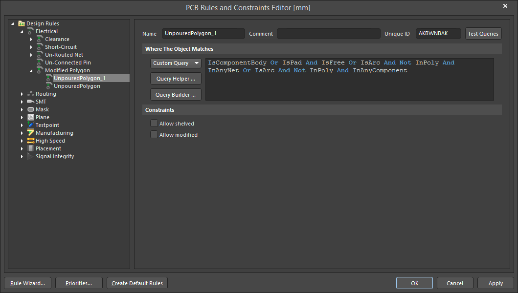
The newly-created rule name can be seen selected in the left side navigation tree. The rule query expression is in the dialog's top-right pane.
A rule of the chosen type is created and the main editing window for the rule is displayed, ready for you to define specific constraints for the rule. The query expression from the PCBLIB Filter panel is entered into the Full Query region of the dialog. Refine the rule configuration settings as required, and apply the new rule.
Applying and Clearing the Filter
Once you have defined the query and set up the options in the panel as required, the filter can be applied either by clicking the panel's Apply button or pressing Enter.
To clear the currently-applied filter from within the panel, clear (select and delete) the query expression in the central region of the panel then either click the Apply button or press Enter. All objects in the design workspace will be restored to full visibility and be available for selection/editing.
Right-click Menus
Right-click within the PCBLIB Filter panel to access to additional options and commands via pop-up menus.
Right-clicking in the Object or Layer region of the panel opens the following context menu options:
- Toggle Check - enable to toggle options. Currently selected options will be deselected, while deselected options will be selected.
- Check All - enable to select all available options.
- Uncheck All - enable to deselect all available options.
Tips
General
- Pressing the F12 key will toggle the visibility of the panel in the workspace.
- The Query Builder (Building Query from Board dialog) provides a simple method of constructing a query using sensitive condition types and values that only allow you to build using relevant 'building blocks'. For advanced query construction with full keyword specification and operator syntax, use the Query Helper dialog.
- As the display options for objects passing and not passing the applied filter are separated, you can effectively apply new filter queries to build upon the results of previous filtering.
When Building Query Expressions
- It is highly advisable to use brackets whenever there is any possibility that the query might not be correctly interpreted.
- Brackets have the highest precedence within an order of precedence that has been defined for the various operators provided and that determines how queries are interpreted by the software (whenever the user has not provided brackets). The sequence of this order is as follows:
Brackets
Not
^, *, /, Div, Mod, And
+, -, Or, Xor
=, <>, <, >, <=, >=
&&, ||
This order of precedence is similar to that used in Pascal type languages. However, generous usage of brackets removes doubt and makes the resulting queries easier to read by others. - Ambiguities are resolved by working from left to right.
- Parentheses are evaluated from inside to outside and equal levels are done left to right.