
Working with a Compiler Generated Junction Object on a Schematic Sheet in Altium NEXUS
This document is no longer available beyond version 4. Information can now be found here: Compiler Generated Junction for version 5
Parent page: Schematic Objects
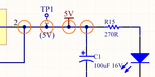
The schematic compiler automatically adds junctions at each T-junction to
complete the electrical connection.
Summary
A junction is an electrical design primitive. It is a small circular object used to join intersecting wires (or buses, or signal harnesses) on a schematic sheet. A Compiler generated junction is a junction that is automatically placed by the Auto-junctioning feature when two wires/buses/signal harnesses are connected in a T-type fashion, or when a wire/bus/signal harness connects orthogonally to a pin, power port or other electrical object.
Availability
This type of junction is placed automatically by the Schematic Editor's Auto-junctioning feature. As such, it is not a design object that can be accessed and placed by the user.
Placement
Compiler generated junctions are placed automatically whenever a T-junction occurs during wiring, such as 2 wires/buses/signal harnesses meeting in a T, or a wire/bus/signal harness orthogonally crossing the end of a component pin or another electrical object, such as a Power Port.
Editing
A Compiler generated junction cannot be edited in the usual manner (via a dialog or graphically on the schematic sheet). The display properties of compiler generated junctions are configured on the Schematic - Compiler page of the Preferences dialog, as shown in the image below. Note that disabling the display of compiler generated junctions does not break the electrical connection at that junction point.
 in the Preferences dialog.") Configure the display options for compiler generated junctions (auto-junctions) in the Preferences dialog.
Configure the display options for compiler generated junctions (auto-junctions) in the Preferences dialog.
Indication of New Auto-Junction Creation
Depending on the affected wiring, performing a drag operation may result in the creation of auto-junctions at new locations. To provide visual feedback on where these new juntion instances will be, hotspots are used. Enable the use of these hotspots, and specify their color - for wires and buses - also as part of your preferences.
 Control the display of predicted auto-junctioning during drag operations.

Example showing predicted new auto-junctions resulting from a drag operation.
Visual Indication of Connectivity Change
While dragging a component, it is possible to inadvertently drag a little to far, or off-course, resulting in an unintended auto-junction, and a potentially fatal change to the connectivity of a circuit. To provide a timely and graphical indication of the status of connectivity while performing a drag, a couple of icons are used:
 - OK - the drag operation is not altering the connectivity of the circuit.
 - Alert - the drag operation is causing a change to the connectivity of the circuit.
The applicable icon is displayed near to the cursor as you drag.

Providing a visual warning that a drag operation will result in a change to connectivity.