
Configuring Schematic Line Object Properties in Altium NEXUS
Created: 十月 18, 2019 | Updated: 十月 18, 2019
| Applies to version: 2.1
您正在阅读的是 2.1. 版本。关于最新版本,请前往 Configuring Schematic Line Object Properties in Altium NEXUS 阅读 4 版本
Parent page: Polyline
Schematic Editor object properties are definable options that specify the visual style, content and behavior of the placed object. The property settings for each type of object are defined in two different ways:
- Pre-placement settings – most Polyline object properties, or those that can logically be pre-defined, are available as editable default settings on the Schematic - Defaults page of the Preferences dialog (accessed from the
 button at the top-right of the workspace). Select the object in the Primitive List to reveal its options on the right.
 - Post-placement settings – all Polyline object properties are available for editing in the Properties panel when a placed Polyline is selected in the workspace.

 The Polyline default settings in the Preferences dialog and the Polyline mode of the Properties panel
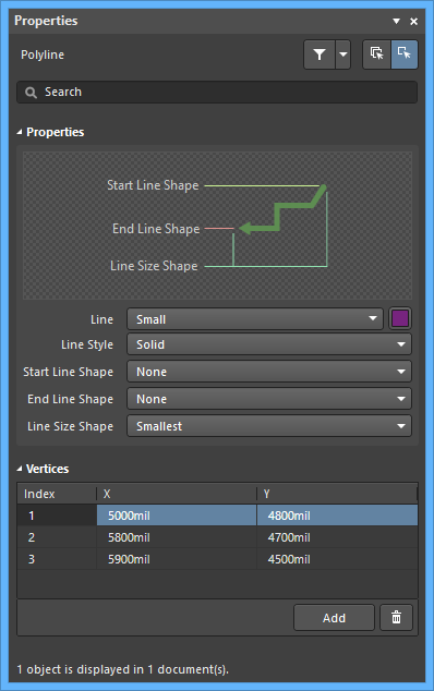
Properties
- Line - use the drop-down to select the desired line. Choices are: Smallest, Small, Medium, and Large. Click the color box to select the desired color for the object.
- Line Style - use the drop-down to select the line style. Choices are: Solid, Dashed, Dotted, and Dash dotted.
- Start Line Shape - use the drop-down to select the shape of the beginning of the line. Choices are: None, Arrow, Solid Arrow, Tail, Solid Tail, Circle, and Square.
- End Line Shape - use the drop-down to select the the shape of the ending of the line. Choices are: None, Arrow, Solid Arrow, Tail, Solid Tail, Circle, and Square.
- Line Size Shape - use the drop-down to select the the shape of the line size. Choices are: Smallest, Small, Medium, and Large.
Vertices (Properties panel only)
- Vertices Grid - lists all of the vertex points currently defined for the object in terms of:
- Index - the assigned index of the vertex (non-editable).
- X - the X (horizontal) coordinate for the vertex. Click to edit.
- Y - the Y (vertical) coordinate for the vertex. Click to edit.
- Add - click to add a new vertex point. The new vertex will be added below the currently focused vertex entry and will initially have the same X,Y coordinates as the focused entry. Click
 to remove the currently selected vertex.