
差异面板
Parent page: System & Environment Panels

The Differences panel displays a hierarchical view of document differences.
Summary
The Differences panel is used to display the logical or physical differences found by the software's built-in Differences Comparator when comparing design documents (for example, when comparing the source document hierarchy (schematics) for a project against the PCB design document). The panel allows you to interactively explore the differences before the decision to create an Engineering Change Order (ECO) that will be used to synchronize the project documents.
Panel Access
To open the Differences panel:
- Click View » Panels » Differences.
- Click the Panels button on the bottom right-hand side of the editor then click Differences.
Displaying Differences
How the Differences panel is applied depends on whether the goal is to:
- Analyze the integrity of the complete project in terms of its content and structure by detecting logical differences within the project hierarchy.
- Compare two versions of the same Schematic or PCB document by detecting their graphical (physical) differences.
Displaying Logical Differences
Comparison of project documents for logical differences is done in the Choose Documents To Compare dialog, activated by right-clicking on a project (or project document) in the Projects panel then selecting Show Differences from the associated context menu.
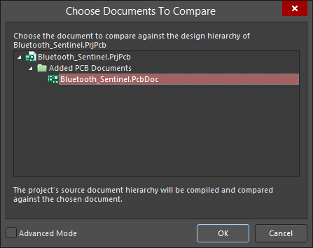
Right click on a project name then select Show Differences to open the Choose Documents To Compare dialog.
Typically, the PCB document would be compared against the source document hierarchy for the parent project to detect logical differences between the schematic design content and the PCB design content.
After clicking OK, if any differences exist between the nominated documents, the Differences between dialog will open. Information in the Differences panel will only appear after clicking the Explore Differences button in the Differences between dialog.
The Differences panel will display only the differences that are listed in the Differences between dialog. These, in turn, are determined by the selections made in the Comparator tab of the Project Options dialog (Project » Options). This tab lists all of the comparison types, such as differences associated with Components, Nets and Parameters. Setting the Mode for each comparison category between Find Differences or Ignore Differences will determine if the Differences Comparator passes its results into the Differences between dialog.

Set up how the differences are detected and reported in the Project Options dialog.
The Differences panel displays the differences found between source documents in a tree-like structure, where the top-level folder displays the total number of differences detected. Sub-folders are then created for each specific comparison type that appears in the Differences between dialog. Each sub-folder lists the specific differences that have been found, which, in turn, are broken down further into objects on the documents that are responsible for creating those differences.
If the associated document is open (or open and hidden), clicking on an object entry in the panel will cross-probe to the object on the document.
The visual display of the object uses the zoom and dim effect where the object is highlighted by dimming all other objects. The contrast of the dimming can be varied with the Dimming slider found in the Highlight Methods region of the System - Navigation page of the Preferences dialog.
Displaying Physical Differences
The graphical (physical) comparison of two versions of the same schematic or PCB document is carried out basically in the same way as the logical comparison outlined above, but also makes use of the Advanced Mode in the Choose Documents To Compare dialog.
Perform a document physical comparison using the Show Differences command (Projects panel right-click menu) to open the Choose Documents To Compare dialog then check the Advanced Mode box. With all project files now shown in the dialog, select the two variations of a document for comparison.
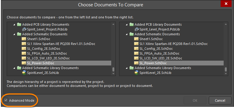
Selecting documents for physical comparison from the Choose Documents To Compare dialog in Advanced Mode.
Clicking OK will proceed with the graphical comparison and open the Differences between dialog as outlined previously. Click Explore Differences to open the interactive differences list in the Differences panel.
The panel displays the differences found between the documents in a tree-like structure. The top-level folder displays the total number of differences detected. Entries are created for each type of difference, which, in turn, contains the specific references and the object (port, part, etc.,) involved for each.
Selecting the object entry for a detected difference will highlight and zoom to the object in the editor workspace.
Tips
- If an object in the panel resides on a document that is currently hidden, the document will be opened automatically and made the active document in the design editor window when you click the associated entry.
- The filtering applied when cross-probing from the Differences panel is temporary. As such, you are not prevented from selecting or editing design objects that fall outside the scope of the filter.
- The information in the Differences panel will be cleared when performing a new document comparison or compiling the parent project.