
项目面板
This document is no longer available beyond version 4. Information can now be found here: Projects Panel for version 5
Parent page: Working with Panels

The Projects panel
Summary
The Projects panel displays all projects that are currently open. Any open documents that have not been created as part of a project or added to an existing open project will be listed.
Panel Access
The Projects panel is accessed in the following ways:
- Choose View » Panels » Projects from the main menus.
- Click the Panels button at the bottom right of the design space then click Projects.
Project Groups
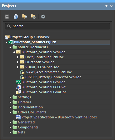
In Altium NEXUS, you may open and edit multiple projects, and if desired, save the collective set projects as a Project Group (.DsnWrk). This may be of particular advantage when the set of projects are related or linked, such as a product design that is composed of multiple PCBs. Creating a Project Group that includes all the relevant projects allows you to open, manipulate and save multiple projects as a single entity. In the Projects panel, the uppermost entry displays the current Project Group – either the default one or one you have created or opened.
- To save the currently opened set of projects as a group select File » Save Project Group As from the main menus.
- To open an existing group, select File » Open Project Group from the main menus, or right-click in the panel and select Open Project Group from the context menu. Use the same access for the Save Project Group command.
- To create a new Project Group, select File » New » Design Project Group from the main menus – this will load the default (blank) Project Group (
Project Group 1.DsnWrk). The same method can be used to close the current Project Group file. - When opening a different Project Group the current group will close. You will be prompted to save any unsaved documents, projects, or changes to the current group first.
- To add another project to a Project Group, open or create a project and then save the current Project Group. Alternatively, right-click in the panel and select the Add Existing Project option.
- In the Projects panel, the uppermost entry displays the current Project Group – either the default one (
Project Group 1.DsnWrk), or one you have created or opened.

A set of related local projects as a Project Group.
Projects within the Projects Panel
Altium NEXUS also supports the concept of projects that are stored entirely within a connected Workspace. Projects can be created as, or converted to, Workspace projects that are hosted in a secure version-controlled repository within the Workspace. This approach greatly simplifies the process of managing project storage, versioning, lifecycle, and implementing design collaboration. Projects will be stored in the Projects panel under the Workspace they are hosted on, rather than the Project Group, as local projects are. When connected to a Workspace, the Workspace icon (  /
/  ). When the local working copy of a project is opened but the Workspace where the project resides is not connected, a grayed-out Workspace icon (
  /
/  ) will appear.

An example of a project within a Workspace in the Projects panel.
Shared Project Icons
 |
This icon appears next to the .PrjPcb document file while connected to the Workspace in which the shared project resides. |
 |
This icon appears next to the .PrjPcb document file when not connected to the Workspace in which the shared project resides. |
To access the context menu regarding your Workspace, right-click on your Workspace name or click the  control at its far right. These commands include:
- Open Project – opens the Open Project dialog.
- Create Project – opens the Create Project dialog.
- Show in Explorer – opens the Explorer panel.
- Show in Web Browser – opens the Projects page of the Workspace's browser interface in your default Web Browser.
- Sign out – signs you out of the Workspace.
When signed out of a Workspace, right-click the Workspace you want to connect to, and click the Sign In command.
► To learn more about Workspace projects, visit the Design Management with a Connected Workspace page.
Project Documents Tree
When you open an existing project or create a new one, its entry will appear in the Projects panel. Any existing documents that are part of a project (and any new ones that have been added) will appear under sub-folders according to their purpose and/or type. For example, the following common folders and content document types can appear under a project:
- Source Documents – core design documents such as schematics, PCBs, etc.
- Settings – provides various files used within the project, including Output Job Files, Harness Definitions Files, and Annotation Documents, among other pertinent files.
- Libraries – local source library documents. Documents are further sub-divided based on library type (e.g., schematic libraries, PCB libraries, etc.).
- Documentation – additional documents that have been added to the project, of a type that is known by Altium NEXUS (e.g., text, PDF, etc.).
- Other Documents – additional documents that have been added to the project, of a type that is not known by Altium NEXUS. These can be opened by Altium NEXUS if the owner application is known by Windows (eg, Word documents, Excel spreadsheets, etc).
- Generated – documents generated as output. Documents are further sub-divided based on type (e.g., BOM documents, text documents, etc.). As project output is generated, the corresponding sub-folders in the main tree will be created and become populated.
- Components – this folder lists each component (grouped by the first letter in the designator), and the number of components whose designator starts with that letter in the project. Validate the project if this folder does not appear (Project menu).
- Nets – this folder lists each net used in the project. Validate the project if this folder does not appear (Project menu).
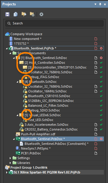
Automatic Sheet Numbering
Automatic sheet numbering can be applied to schematic sheets directly in the Projects panel. Drag and drop schematic sheets in the panel to change the numbering. The sheet numbering displays to the left of the schematic sheet name as highlighted in the image below.
The automatic sheet numbering feature can be enabled/disabled using the Automatic Sheet Numbering (Project Option) option in the Sheet Numbering For Project dialog and the Automatic Sheet Numbering option on the Options tab of the Project Options dialog.
Working in the Documents Tree
- Any documents that are independent of a project will appear as Free Documents and will appear under corresponding sub-folders. By right-clicking on a free document and choosing the Add to Project <ActiveProjectName> command from the context menu, you can add a currently open free document to the active project. Alternatively, you can drag and drop it onto the required project name, in the Projects panel.
- Along with allowing multiple documents to be open for editing, the environment also supports multiple projects being open at the same time. These could be related or unrelated projects.
- Documents in the Projects panel are automatically arranged in logical groups or 'folders', such as Source Documents (Schematic, PCB, etc.), Settings documents (Harness, Outjob, etc.,) and, in the case of a hierarchical design, top-level schematic documents. The documents within each folder group are displayed by default in the order they were added but can be dragged and dropped to a new order position within the group.
- In the case of a new hierarchical design, the parent-child relationship between documents will be displayed in the panel. Note that the connectivity relationships cannot be defined by dragging and dropping schematic documents since the inter-sheet connections and design hierarchy are in fact defined by Sheet Symbols and Port definitions.
- The project document sub-folders, whether expanded or closed, share these right-click menu commands:
- Open All – used to open all documents within the focused project document sub-folder.
- Close All – used to close all documents within the focused project document sub-folder.
- Save All – used to save all documents within the focused project document sub-folder.
- Remove All – used to remove all documents within the focused project document sub-folder. Use the following Remove from project dialog to select how the documents should be removed.
- Refresh – used to update the panel with any changes you have made.
The right-click options listed below are pertinent only to files found within the specified project document sub-folders:
Libraries
- SVN Database Library Maker – used to access the SVN Database Library Conversion Wizard, from the currently focused project library document – either a Schematic Library (
*.SchLib), PCB 2D/3D Component Model Library (*.PcbLib), or an Integrated Library (*.IntLib).
Components, Nets
- Cross Probe to Schematic – used to cross-probe from the selected component or net entry in the Projects panel to that entity on the source schematic document(s) of the parent PCB design project.
- Cross Probe to PCB – used to cross-probe from the selected component or net entry in the Projects panel to that entity on the PCB document of the parent PCB design project.
- Component Grouping – used to quickly access the Components Grouping controls for the Projects panel.
Active Versus Focused
In the panel's main tree, the active project is highlighted. When there are no documents open in the design editor window, a project is made active by selecting it from a list of all currently open (loaded) projects in the panel. As soon as a project document is opened (in an editor/viewer), the parent project of that document automatically becomes the active project. The active document in the design editor window will also be highlighted in the panel.

The highlighting of an open active document and its active parent project.
With numerous documents open in the design editor window, changing the active document using the editor's document tabs will cause the Projects panel to update accordingly, i.e. to reflect both the active document and the active project (if the document made active does not reside in the same project as the previously active document). Conversely, clicking on the entry for a document that is already open (and that belongs to a non-active project) will make the parent project of that document the active project.
Only one project and document may be active at any given time, however, the panel allows you to focus and perform actions on any project or document. Right-clicking on the entry for a non-active project or a non-active document will bring up an associated menu with commands targeting the focused project or focused document, respectively.
In the case of focusing a document, the document will only become focused if it is closed, otherwise, it will become the active document and its parent project will become the active project. For example, in the image below, the active project is MiniPC.PrjPcb and the active document DDR4.SchDoc. The focused document is Ethernet-HPS.SchDoc (distinguished in the panel by a dotted outline box).
 and a selected focused document indicated by the dotted outline.")
An opened active document (blue) and a selected focused document indicated by the dotted outline.
Quick Access Controls
 |
This command is used to locally save the currently focused project. |
 |
This command is used to validate all source documents of the focused project. |
 |
This command is used to open an instance of Windows Explorer, at the location where the focused file is stored. |
 |
This command is used to access Project Options – Options dialog, from where you can set up project-specific options for the focused project. |
 |
This command is used to quickly access controls relating to the behavior of the Projects panel. Descriptions of the controls are located on the System – Projects panel page of the Preferences dialog. |
There are several right-click menu options that appear within the quick access controls section of the Projects panel. When not actually right-clicking on one of the quick access control buttons, but merely around blank areas of the panel that do not house icons or documents, the following options appear:
- Recent Project Groups – hover to unveil a list of Design Project Groups (
*.DsnWrk) that have recently been opened. - Add New Project – used to create a new design project (PCB or Multiboard).
- Add Existing Project – used to open any existing Altium NEXUS project.
- Open Project Group – used to open any existing Design Project Groups.
- Save Project As – used to save the current Design Project Group.
- Rename – used to rename the currently active Design Project Group in the Projects panel with a new name.
- Save All – used to locally save all projects and documents that have been modified.
- Explore – used to open an instance of Windows Explorer, at the location where the current Design Project Group is stored.
- Refresh – used to update the Projects panel.
Direct Editing Content Types from the Projects Panel
Various content types may be edited directly from the Projects panel thanks to a Workspace that provides a flexible and secure method of centralizing the storage and management of all types of design data used in Altium NEXUS. Direct editing avoids the need to work with a separate version-controlled source data since it allows you to edit a supported content type using a temporary editor loaded with the latest source direct from the Workspace itself. Once editing is complete, the entity is saved (or re-saved) into a subsequent planned revision of its parent content type, and the temporary editor closed. There are no permanent files on your hard drive, no questioning whether you are working with the correct or latest source, and no having to maintain separate version control software. The Workspace handles it all, with great integrity, and in a manner that greatly expedites changes to your data.
The following content types are supported with respect to Direct Editing:
- Component
- Footprint
- Symbol
- Simulation Model
- Managed Schematic Sheet
- Layerstack
- Schematic Template
- Project Template
- Component Template
- Outputjob
- Draftsman Document Template
- Draftsman Sheet Template
When these content types are being edited within the Projects panel, they will be listed under the Workspace in which they reside. Right-clicking on these content types provides various options:
- Component Rule Check – used to run a manual validation check for the component(s) currently being edited in the Component Editor. At the heart of the validation process is the powerful Component Validator, which tests for an array of potential issues with the component and its defined models – both hardwired tests, as well as a range of violation types that can be user-defined at the global level, on the Data Management – Component Rule Checks page of the Preferences dialog. After launching the command, the component rule check will be run. Any issues will be flagged as entries in the Messages panel.
- Save to Server – used to save the current content type being edited to the Workspace, storing it as the next revision of that content type, closing the temporary editor, and destroying the temporary file.
- Discard Local Changes – used to cancel direct editing of the active content type, closing the temporary editor, and destroying the temporary file without releasing any changes made since the original editing session was launched.
Design Variants within the Projects Panel
When a product needs to be designed and produced as a number of variations of that product, say where each has different options or capabilities, the ability to implement Design Variants avoids the need to create a unique version of the design for each variation.
In practice, a design variant uses the same base design, but the PCB assembly is loaded with the set of components specified by the variation. A variation may then be nominated when generating the design’s manufacturing output (BOM, P&P, Assembly drawings, etc.,), which will, in turn, determine how the product is assembled.
To examine design variations, double click on the required variant in the Projects panel and switch to a compiled (physical design) tab of the schematic. The compiled tab displays a different Active Bar at the top of the design space, which includes variant-specific buttons. These buttons are only available when a variant is selected in the Projects panel. See the picture below for an example of these options.

The schematic editor's physical design view. The dim level for the un-editable objects is set in the Schematic – Compiler page of the Preferences dialog.
The right-click options on the Variant sub-folder includes:
- Variants – used to open the Variant Management dialog.
- [No Variations] – click to display the document with no variants.
- <Variant Name> – click to display the specifically chosen variant.
Left-clicking on a specific variant within the Variant sub-folder displays the desired variant. You may also utilize the Set as current command to display the desired variant, which is available when right-clicking on the desired variant within the Variant sub-folder.
► To learn more about design variants, visit the Design Variants page.
Make an Existing Local Project Available Online
You can also make a local project (regular project, or a project currently under version control) available to the connected Altium 365 Workspace – essentially 'registering' the project with the Workspace and creating a 'mirror' of it. This allows you to enjoy the collaborative features available through the Altium 365 platform while keeping your original project right where it is. To do this, open the existing local project as normal in Altium NEXUS, then right-click on its entry in the Projects panel and select Make Project Available Online from the context menu, giving access to the Make Available Online dialog.

Make an existing local project available to the Workspace, essentially 'registering' it with the Workspace and creating a 'mirror' of it.
Use the Make Available Online dialog to change the project Name and add a Description. By default, the name will be that of the original project.
Check the Version Control option to add the project under the Workspace's own built-in VCS (Git). This option is unchecked by default, where the project files will simply be stored in the Workspace for basic access and to enable sharing with others for viewing and commenting only – a less formal Simple Sync as it were. It is recommended to enable formal version control, as by doing so you will have access to the maximum functionality offered through, and by, the Workspace and the Altium 365 platform.
Click the Advanced link to expose the Folder field. This field is used to specify where the folder for the mirrored project – within the Workspace's folder structure – is to be created. The default path for new projects is specified on the Admin – Settings – Projects page of the Workspace's browser interface (by default, this will be Projects\<ProjectName>). Click the  button to browse to and select a different Workspace folder, if required.
With the properties for the mirrored project defined as required in the Make Available Online dialog, click OK. Projects that have been made available online – in the Workspace – will be shown in the Altium NEXUS Projects panel as follows:
-
For a project that is not under external version control and when made available online the Version Control was left unchecked, the project is shown with the
 icon only. This indicates the project as being registered with the Workspace, that a mirrored project exists, and that the two are synchronized using the Simple Sync methodology. Saved local files are automatically synchronized with their mirrored project counterparts in the Workspace.
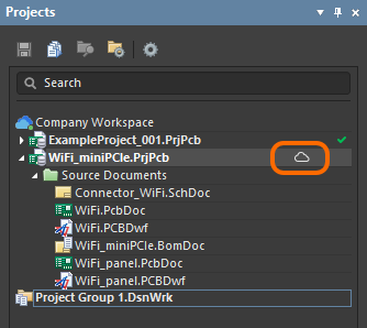
-
For a project that is under external version control, the project is shown with the
icon to indicate the project as being registered with the Workspace, that a mirrored project exists, and that the two are synchronized using the Simple Sync methodology. Associated  icons reflect the fully synchronized state that exists between the external design repository and the local working copy. Once local file changes are saved and committed to the external design repository, those changes are automatically synchronized with their mirrored project counterparts in the Workspace.
-
For a project that is not under external version control and when made available online the Version Control was checked, the project and files will be committed and pushed to the Workspace's
Versioned Storagedesign repository, with the Projects panel reflecting the fully synchronized state that exists between that remote design repository and the local (working copy) repository, as indicated by the associated icons. Changes made to the design must be committed back to the repository in the Workspace.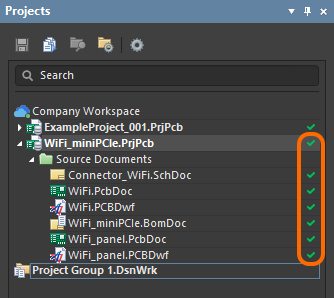
The mirrored project will subsequently be available from the Projects page of the Workspace's browser interface.
Simple Sync States
Where a local project is made available online to an Altium 365 Workspace using the Simple Sync approach (not using the Workspace's formal version control), the current state of the synchronization between local and Workspace-side projects is presented in the Projects panel through a range of icons. These icons, and their meaning, are as follows:
 |
Synchronized | The local project and the mirrored project in the Workspace are synchronized. |
 |
Sync-in-progress | Changes made to the local project are being synchronized to the mirrored project in the Workspace. For a local project not under external VCS, this occurs when saving a local file. For a local project under external VCS, this occurs when saving and committing local file changes to the external design repository. |
 |
Project is Read-only | The project has been shared with you, but you have Read-only access to it. Under the Simple Sync methodology, the design project can be edited by a single person only (the owner of that project – the one who made it available online to the Workspace). |
 |
Not Synchronized | Changes have been made locally, but these have not been synchronized yet with the mirrored project in the Workspace. This can happen, for example, when the same project is open for editing by the owner/author on two computers (PC1 and PC2). On PC1, the Workspace is subsequently disconnected. On PC2, connection to the Workspace remains and changes are made. On saving the local file(s) the project remains unsynchronized. If you attempt to close the project on PC2, the Closing unsynchronized projects dialog will appear alerting you to this fact. If you choose to close the project, changes will not be available on PC1. To remedy the situation, disconnect from and then reconnect to, the Workspace on PC2. The project will be synchronized with the Workspace. The synchronized data will be reflected on PC1 once the Workspace is connected there too. |
 |
Conflict |
There is a conflict between the data for the local project and the data for the mirrored project in the Workspace. This can happen, for example, when the same project is opened for editing by the owner/author on two computers (PC1 and PC2). On PC1, the project is opened and the Workspace subsequently disconnected. Changes are then made and local files saved. Later, on PC2, the same project is opened and, while still connected to the Workspace, changes are made and saved. Later still, connection is made to the Workspace back on PC1. A conflict exists because there are changes locally on PC1, but the Workspace contains the updated data from changes made and synced on PC2. To remedy the situation, on PC1 right-click on the project and choose the Resolve Conflicts command. The Resolve Conflicts dialog will appear. You have the option to Use Server files (the data from the mirrored project in the Workspace will be used and local modifications will be lost), or Use Local files (the data from the local project will be used and synced to overwrite the current data for the mirrored project in the Workspace). |
Save to Server
When a file that belongs to a project has been modified and saved locally, you can save that file to the Workspace from the Projects panel. Save the selected files by right-clicking on a project and selecting Save to Server or by selecting the Save to Server link next to the project file (.Prj).
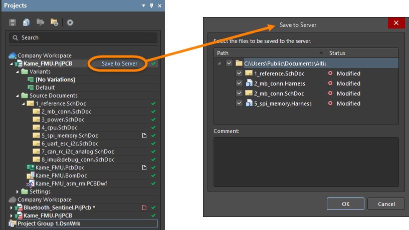
Clicking the link and selecting the command opens the Save to Server dialog in which you can select the documents to be saved. After clicking OK, the documents are saved to the Workspace and the Save to Server link disappears from the Projects panel.
Shared With Me
A project shared with an Altium NEXUS user is accessed from the Shared With Me location option in the Open Project dialog. The user is not required to be a member of the Workspace team.
A project that has been opened from shared access is indicated by an associated Shared with me label. The project can be saved back to the Workspace if editing rights have been granted for the shared project or saved locally if the project has been shared with view-only permissions. To open the project the Altium 365's Web Viewer, select the Show in Web Browser option from the project entry's right-click context menu in the Projects panel.

Accessing the Web Viewer for the shared project from the Projects panel.
Document Display Icons
Document entries in the panel are accompanied by icons that indicate their open/modified/version control status. This provides a quick visual summary of which documents are modified, saved, whether they are Workspace or local, and their version control status. The document icons and meanings are listed below.
Open/Modified Status Icons
| [blank] | The document is closed. |
 |
Open – The document is open as a tabbed document in the design editor window. |
 |
Open/Modified – The document is open and has been modified (yet to be saved). |
 |
The document file is open and locked by this instance of Altium NEXUS. |
 |
The document file is open and has been locked by another instance of Altium NEXUS. |
 |
The document is being edited by another user. |
 |
The document being edited by another user is currently open in the editor. |
Version Control Status Icons
| [blank] | N/A | The file is not under version control in a VCS repository, |
| |
No modification | The local copy of the file matches the file in the repository and is up to date. |
 |
Scheduled for Addition | A file has been added to version control but not yet Committed (checked in) to the VCS repository. |
 |
Modified | The local copy of the file has been modified and saved to the working folder. Commit the file to create a new revision in the repository. |
 |
Out of date | The local copy of the file (in the working folder) is older than its counterpart in the repository and is therefore out of date. Use the Version Control Update option to retrieve the latest file from the repository or save the file, which will create a Conflict condition. |
 |
Conflict | The file has been committed by another user before you have committed your own edited and saved version of that file. Use the Version Control Update or Resolve command to determine which version of the file will become the latest revision in the repository. |
 |
Ahead of server (Git) | The file in the local working repository is newer than its counterpart in the remote Git repository. This occurs when a local file has been modified, saved and committed to the local repository, but not yet Pushed to the remote repository. |
 |
Scheduled for Deletion | The project file has been removed from version control and will be deleted from the VCS repository and database during the Version Control Commit process. This icon also appears when a file is missing from the local working folder (it has been deleted, renamed or moved), which is resolved by re-populating the folder from the repository with the Version Control » Update command. |
 |
Locked | The file has been locked by you or another user. A locked file cannot be updated to a new revision in the repository by another user unless it is forced to be unlocked. This state can be associated with other icons, such as those for Modified  or No Modification or No Modification , when these status conditions also apply. When locked by you, the file cannot be updated to a new revision in the repository by another user (unless it is forced to be unlocked). While a single icon type is used to flag a locked file, its associated text will indicate who has locked the file – , when these status conditions also apply. When locked by you, the file cannot be updated to a new revision in the repository by another user (unless it is forced to be unlocked). While a single icon type is used to flag a locked file, its associated text will indicate who has locked the file – Locked by me or Locked by someone else. The VCS text will also indicate combined conditions, for example; Modified and locked by me. |
Right-click Menus
Project File
Right-clicking on a project file in the panel provides access to additional options and commands in the right-click menu.

The first image shows the typical right-click menu for a Workspace-based project, while the second image displays the typical right-click menu for a local project.
Right-click selections include:
- Validate PCB Project – the compiling process detects electrical and drafting violations and is integral to producing a valid netlist for a project. Results are displayed in the Messages panel (View » Panels » Messages).
- Make Project Available Online – when connected to your Altium 365 Workspace, this command opens open the Make Available Online dialog, where you may register a project that is not currently under the Workspace's version control.
-
Make Project Available on Server – when signed into your NEXUS Server Workspace, this command opens the Make Available on Server dialog to allow you to make that project available as a project in the Workspace.
- Add New to Project – add a new, blank Schematic, PCB, ActiveBOM, Draftsman, type of library, output job, CAM, or Database link document to the current project.
- Add Existing to Project – add an existing, locally stored Schematic or PCB document to the current project. Other file types (text, etc.,) are also supported.
- Clone – used to clone projects. After launching the command, the Clone Project dialog will display the Project Name and Description. By default, the original project name will be used with the suffix '
- Copy'. - Save – saves the project.
- Rename – rename the project.
- Save to Server – opens the Save to Server dialog, from where you can save locally, modified files.
- Make Active Project – ensures that the desired project becomes the currently active project.
- Close Project Documents – used to close all currently open and/or open and hidden documents associated with the focused project.
- Close Project – closes the project and any active project documents. You will receive prompts to save any documents that have been modified.
- Explore – used to open an instance of Windows Explorer, at the location where the focused project document is stored.
- Show Differences – detect and resolve the difference between two design files.
- Variants – opens the Variant Management dialog to define variations of the base design where components can be configured as fitted or not, or fitted with modified component parameters.
- History & Version Control – opens a menu of history and version control options. Use the Local History (Legacy) submenu option to compare an open document with its last saved contents. Refresh, commit, update, or lock your project. You also can resolve conflicts, revert local modifications, or add/remove from version control. Use the Storage Manager option to open the Storage Manager panel.
- Project Packager – opens the Project Packager Wizard to package files into a portable ZIP file.
- Project Releaser – click to open the Project Releaser.
- Show in Explorer – used to open the Explorer panel Project View for the selected project.
- Show in Web Browser – used to open the web browser interface of a project.
- Share – click to open the Share dialog, where you may share your design projects with others, anywhere around the world, directly from within the software.
- Project Options – click to open the Project Options dialog.
Document Files
Right-click on a document file in the panel to open a pop-up context menu offering a range of document-specific options and commands.
.")
Example right-click context menu for a document (Schematic Library in this case).
Several right-click options are basically the same as when right-clicking on a Project, outlined above. Others include:
- Close – a closed document will no longer be open in the design editor.
- Explore – used to open an instance of Windows Explorer, at the location where the focused project document is stored.
- Add to Project – used to add a currently open free document to the active project.
- Remove from Project – use to exclude the document from the parent project.
- Save – save the document locally.
- Rename – rename the document.
- Page Setup/Print Preview/Print – manage document printing, replicating the functions available from the main Print options (Outputs » Documentation » Print).
- Show Differences – detect and resolve the inconsistencies in the design structure or the difference between two design files.
- History & Version Control – opens a menu of history and version control options. Use the Local History (Legacy) submenu option to compare an open document with its last saved contents. Refresh, commit, update, or lock your project. You also can resolve conflicts, revert local modifications, or add/remove from version control. Use the Storage Manager option to open the Storage Manager panel.
- SVN Database Library Maker – used to access the SVN Database Library Conversion Wizard, from the currently focused project library document – either a Schematic Library (
*.SchLib), PCB 2D/3D Component Model Library (*.PcbLib), or an Integrated Library (*.IntLib). - Migrate Library – used to open the Library Migrator (Simple Migration) dialog, which provides a streamlined process to migrate selected file-based component libraries to your Workspace.
Notes
- Documents can be transferred between projects in the panel by clicking and dragging. The document does not have to be dragged into the correct sub-folder; it will be placed correctly within the project structure automatically.
- The keyboard shortcuts Up Arrow, Home, End, and Down Arrow can be used to display the previous, first, last, and next entry in the panel, respectively. Use the Right Arrow and Left Arrow keys to expand and collapse a top-level entry or its sub-folder, respectively.