
Properties Panel (Draftsman)
Parent page: Draftsman Panels

The Properties panel
Summary
The Properties panel is used to edit properties of a Draftsman document. The panel provides editing access to the detailed properties of objects that have been placed in the drawing document.
Panel Access
The panel is accessed in the following ways:
- Click View » Workspace Panels » Draftsman » Properties.
- Double-click on an open and placed drawing view.
- Select the drawing view and choose Item Properties from the right-click menu.
- Click the
 button at the bottom-right of the work area.
Content and Use
You can select an object or view to see its properties in the panel. The panel automatically changes its mode and content to match the selected drawing view or object.
Use  to open/close the region listed to the left of the arrows.
Each mode of the panel is explained in the following sections.
Board Assembly View
This mode shows the board outline with cutouts, holes, and component graphics with additional notation. The component graphics are automatically generated and take data on a priority basis from the following sources:
- The projection of a board component's three-dimensional model (3D model) – used by default.
- A component's silk screen graphic taken from Top/Bottom Overlay layer – used when a 3D model is not available.
- A graphic of the component's dimensions derived from its contact pads (its Bounding Box) – used when both a 3D models and screen overlay are not available.

The Board Assembly View mode of the Properties panel
- Position – sets the object's rotational orientation to choices of 90º increments.
- Rotation – use the drop-down to select the rotation: 0º, 90º, 180º, or 270º.
- Scale – sets the visible size of the object.
- Scale – use the drop-down to select from preset ratios. This option is not available if Use Custom Scale is enabled.
- Use Custom Scale – use to set a specific scale, relative to
1, where0.9would represent 90%.
- Title – sets a view's title name, its font/color and visibility settings. System or custom parameters can be used in the title.
- Show Title – enable to show the title.
- Title – enter the title name.
- Use Document Font – enable to force the placed view to adopt the font style defined in the global Draftsman Document Options dialog.
- Title Font – use
 to open the Font dialog to select the desired font. This option is available only when Use Document Font is not checked.
 - Title Color – use the drop-down to select the color for the title.
- Styles – sets the color and line weight/style for the board and component outlines.
- Component Line Style – use to open the Line Style dialog to choose the line style for components.
- Board Line Style – use to open the Line Style dialog to choose the line style for the board.
- Component Line Style – use
- Font – the font settings for component designators, which also defines the minimum and maximum size for the automatic scaling to fit into component graphics.
- Use Document Font – enable to force the placed view to adopt the font style defined in the global Draftsman Document Options dialog.
- Font – use to open the Font dialog to select the desired font.
- Minimum size, pt – enter the minimum point size of the font.
- Maximum size, pt – enter the maximum point size of the font.
- Font – use
- View – use the following options to configure the view settings:
- View – use the drop-down to select the direction of view: Top, Bottom, Left, Right, Front, or Back.
- Display holes – use the drop-down to select how to display holes:
- None – show no holes.
- All – show all holes.
- Pads only – show only construction holes.
- Minimum diameter only – show only large holes.
- Minimum Diameter – if Minimum diameter only was selected for Display holes, enter the size threshold setting.
- Variation – where available, select a project PCB Variant to display. Omitted variant components are not shown or are indicated as a (green) mesh, as determined by the related Draftsman Document Options dialog setting.
- Component Caption – select the parameter source for the text captions associated with components (Designator or BOM Item Position) from the drop-down.
- Show SMD Pads – check to display surface mount component pads in the drawing. Use the associated drop-down menu to select the rendering color.
- Show Through-Hole Pads – check to display any Through-Hole type pads that exist in the drawing. Use the associated drop-down menu to select the rendering color.
- Show Silkscreen – check to show the board design's Silk Screen overlay on the drawing view, where the correct overlay (Top or Bottom) will be shown for the currently selected View setting. Note that component graphics and designators on the Silkscreen layer are not displayed, as these elements are automatically handled by Draftsman.
- Components – use to open the Component Display Properties dialog to configure how components are displayed.
Board Fabrication View

The Board Fabrication View mode of the Properties panel
- Position – sets the object's rotational orientation to choices of 90º increments.
- Rotation – use the drop-down to select the rotation: 0º, 90º, 180º, or 270º.
- Scale – sets the visible size of the object.
- Scale – use the drop-down to select from preset ratios. This option is not available if Use Custom Scale is enabled.
- Use Custom Scale – use to set a specific scale, relative to
1, where0.9would represent 90%.
- Title – sets a view's title name, its font/color and visibility settings. System or custom parameters can be used in the title.
- Show Title – enable to show the title.
- Title – enter the title name.
- Use Document Font – enable to force the placed view to adopt the font style defined in the global Draftsman Document Options dialog.
- Title Font – use to open the Font dialog to select the desired font. This option is available only when Use Document Font is not checked.
- Title Color – use the drop-down to select the color for the title.
- View – use the following options to configure the view settings:
- Layer – use the drop-down to select the board layer displayed.
- View Side – use the drop-down to select the view, either Top or Bottom.
- Drawing Mode – how board conductors are displayed. Use the drop-down to select the drawing mode, either Full (solid and fully rendered) or Simplified (as lines).
- Polygon Fill Mode – how polygons are displayed. Use the drop-down to select: Filled (solid) , Hatched (hatching fill) or Outline.
- Board Line Style – the type, color and weight options for the line that defines the board perimeter. Use to open the Line Style dialog to select the line style.
- Show Out of Board Copper – check to allow the view to render any copper areas (tracks, fills, ploygons etc) that lie beyond the board outline perimeter.
Board Section View
A Section View provides a profile slice, or sectional, drawing taken from a nominated 'cut' point through a placed PCB Assembly View. The section view generator takes the available 3D data from the current PCB to create a standalone section drawing that is aligned to the nominated cut point. Any number of Section Views can be created from an Assembly View, and the section parameters may be modified after they are placed.
This mode of the panel provides options for a selected Section View, such as its scale, label, style, and orientation.
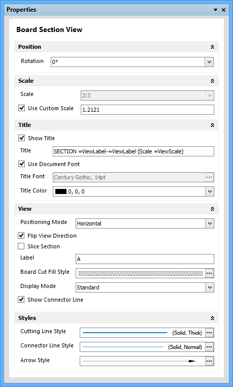
The Board Section View mode of the Properties panel
- Position – sets the object's rotational orientation to choices of 90º increments.
- Rotation – use the drop-down to select the rotation: 0º, 90º, 180º, or 270º.
- Scale – sets the visible size of the object.
- Scale – use the drop-down to select from preset ratios. This option is not available if Use Custom Scale is enabled.
- Use Custom Scale – use to set a specific scale, relative to
1, where0.9would represent 90%.
- Title – sets a view's title name, its font/color and visibility settings. System or custom parameters can be used in the title.
- Show Title – enable to show the title.
- Title – enter the title name.
- Use Document Font – enable to force the placed view to adopt the font style defined in the global Draftsman Document Options dialog.
- Title Font – use to open the Font dialog to select the desired font. This option is available only when Use Document Font is not checked.
- Title Color – use the drop-down to select the color for the title.
- View – use the following options to configure the view settings:
- Positioning Mode – changes the cut orientation. Use the drop-down to select the positioning mode, either Horizontal or Vertical.
- Flip View Direction – changes the directional view of the selected section cut (the direction from which you are 'looking'). The cut line direction arrows will change accordingly.
- Slice Section – enables/disables the visibility of the objects behind the cut line – it removes the 'background' objects from the section view.
- Label – enter the desired label for the view.
- Board Cut Fill Style – sets the properties of the graphical pattern superimposed on cut objects, and therefore the appearance of the sliced object faces. Use to open the Fill Style dialog to select the style.
- Display Mode – sets the cut line end arrow style. Use the drop-down to select the display mode, either Standard or Alternative.
- Show Connector Line – toggles the line drawn between the cut arrows.
- Styles – use to determine the visual style of the cut line placed on the Assembly View.
- Cutting Line Style – use to define the line's weight, style and color. Use to open the Line Style dialog to select the style.
- Connector Line Style – sets the properties of the line drawn between the cut arrows. Use to open the Line Style dialog to select the line style for connectors.
- Arrow Style – use to set the shape and weight of the cut arrow heads. Use to open the Arrow Style dialog to select the line style for arrows.
- Cutting Line Style – use to define the line's weight, style and color. Use
Board Detail View
This mode of the panel provides options for the magnification factor (scale), labeling and line attributes of the detailed view.

The Board Detail View mode of the Properties panel
- Position – sets the object's rotational orientation to choices of 90º increments.
- Rotation – use the drop-down to select the rotation: 0º, 90º, 180º, or 270º.
- Scale – sets the visible size of the object.
- Scale – use the drop-down to select from preset ratios. This option is not available if Use Custom Scale is enabled.
- Use Custom Scale – use to set a specific scale, relative to
1, where0.9would represent 90%.
- Title – sets a view's title name, its font/color and visibility settings. System or custom parameters can be used in the title.
- Show Title – enable to show the title.
- Title – enter the title name.
- Use Document Font – enable to force the placed view to adopt the font style defined in the global Draftsman Document Options dialog.
- Title Font – use to open the Font dialog to select the desired font. This option is available only when Use Document Font is not checked.
- Title Color – use the drop-down to select the color for the title.
- View – use the following options to configure the view settings:
- Label – enter the desired label for the view.
- Display Mode – use the drop-down to select the display mode: Connected, With Leader, or No Leader.
- Styles – sets the color and line weight/style for the board.
- Connection Line Style – use to open the Line Style dialog to select the line style for connections.
- Source Border Line Style – use to open the Line Style dialog to select the line style for the source border.
- Detail Border Line Style – use to open the Line Style dialog to select the line style for the detail border.
- Connection Line Style – use
Drill Table

The Drill Table mode of the Properties panel
- Title – sets the title name, its font/color and visibility settings. System or custom parameters can be used in the title.
- Show Title – enable to show the title.
- Title – enter the title name.
- Use Document Font – enable to force the placed view to adopt the font style defined in the global Draftsman Document Options dialog.
- Font – use to open the Font dialog to select the desired font. This option is available only when Use Document Font is not checked.
- Text Color – use the drop-down to select the color for text.
- Styles – sets the color and line weight/styles.
- Table Line Style – use to open the Line Style dialog to select the line style for the table.
- Even Row Color – use the drop-down to select the color for even rows.
- Non-Even Row Color – use the drop-down to select the color odd rows.
- Use Document Font – enable to use the document font.
- Font – use to open the Font dialog to select the desired font. This option is available only when Use Document Font is not checked.
- Text Color – use the drop-down to select the color for text.
- Show Footer – enable to show the footer.
- Table Line Style – use
- Columns – use the following options to manage the table data sort order, and column visibility and position order.
- Visible – enable the checkboxes of the column captions you want to appear.
- Order – click to toggle the sort order of the column: off, ascending, or descending.
- Up – click to move the selected caption up one position on the list.
- Down – click to move the selected caption down one position on the list.
- Units
- Show Unit Names – enable to show unit names, for example,
10.1mmrather than just10.1. - Dual Units – check to enable two measurements for each dimension, with one set to show the Units type setting and the other showing the Dual Units type setting.
- Primary Precision – use the drop-down to select the precision value from the list.
- Dual Precision – use the drop-down to select the dual precision value from the list.
- Show Unit Names – enable to show unit names, for example,
- Data Filtering
- Layer Pairs – select from the available list of Drill Layer Pairs for the PCB for display.
- Pads / Vias – use the drop-down to select the desired items to filter: Pads, Vias, or All.
- Plated / Non-Plated – use the drop-down to select the desired items to filter: Plated, Non-Plated, or All.
- Drill Symbols
- Configurations – click to open the Drill Symbol Configurations dialog to set the Drill Table's symbol styles, and the grouping of drill hole types under those symbols.

Use the Drill Symbol Configurations dialog to configure the drill symbol graphic.
The Drill Symbol Configurations dialog presents a tabular view of PCB hole data, with hole styles grouped on a selectable parameter (column data) basis and assigned standard symbols.
Table

The Table View mode of the Properties panel
- Title – sets a view's title name, its font/color and visibility settings. System or custom Parameters can be used in the title.
- Show Title – enable to show the title of the drill table.
- Title – enter the title name.
- Use Document Font – enable to force the placed view to adopt the font style defined in the global Draftsman Document Options dialog.
- Font – use
 to open the Font dialog to select the desired font. This option is available only when Use Document Font is not checked.
- Font – use
- Text Color – use the drop-down to select the color for text.
- Show Title – enable to show the title of the drill table.
- Border
- Outer Line - use the first drop-down to select the line type of the outer line border; use the second drop-down to select the color.
- Inner Line - use the first drop-down to select the line type of the inner line border; use the second drop-down to select the color.
- Cell Properties - use to set the prooperties of the cells within a table.
- Column Width - enter the desired column width.
- Cell Background Color - use the drop-down to select the desired background color.
- Cell Padding Vertical - enter the desired vertical cell padding.
- Cell Padding Horizontal - enter the desired horizontal cell padding.
- Use Document Font - enable to force the placed view to adopt the font style defined in the global Draftsman Document Options dialog.
- Font - use to open the Font dialog to select the desired font. This option is available only when Use Document Font is not checked.
- Text Color - use the drop-down to select the color for text.
- Horizontal Alignment - select the desired alignment for text.
Drill Drawing View
With a placed Drill Drawing graphic selected in the editor, this mode of the panel offers the standard drawing view settings, such as Position, Title and View.

The Drill Drawing View mode of the Properties panel
- Scale – sets the visible size of the object.
- Scale – use the drop-down to select from preset ratios. This option is not available if Use Custom Scale is enabled.
- Use Custom Scale – use to set a specific scale, relative to
1, where0.9would represent 90%.
- Title – sets the title name, its font/color and visibility settings. System or custom parameters can be used in the title.
- Show Title – enable to show the title.
- Title – enter the title name.
- Use Document Font – enable to force the placed view to adopt the font style defined in the global Draftsman Document Options dialog.
- Title Font – use to open the Font dialog to select the desired font. This option is available only when Use Document Font is not checked.
- Title Color – use the drop-down to select the color for the title.
- View – use the following options to configure the view settings:
- View – use the drop-down to select the view, either Top or Bottom.
- Rotation – use the drop-down to select the rotation: 0º, 90º, 180º, or 270º.
- Layer Pairs – select Drill Layer Pairs for the PCB (where available) from the drop-down for display in the drawing view.
- Board Line Style – the type, color and weight options for the line that defines the board perimeter. Use to open the Line Style dialog to select the line style.
- Configurations – click to open the Drill Symbol Configurations dialog to set the drill symbol graphic and its size for each hole style group.
Use the Drill Symbol Configurations dialog to configure the drill symbol graphic.
The Drill Symbol Configurations dialog presents a tabular view of PCB hole data, with hole styles grouped on a selectable parameter (column data) basis and assigned standard symbols.
The dialog's hole data table provides a flexible approach to assigning holes styles to Drill Drawing symbols, along with setting the symbol display graphics and sizes. By using the selectable hole parameters offered by the Grouping drop-down menu, the chosen criteria will group hole types under one symbol.
Bill of Materials

The Bill Of Materials mode of the Properties panel
- Title – sets the title name, its font/color and visibility settings. System or custom parameters can be used in the title.
- Show Title – enable to show the title.
- Title – enter the title name.
- Use Document Font – enable to force the placed view to adopt the font style defined in the global Draftsman Document Options dialog.
- Font – use to open the Font dialog to select the desired font. This option is available only when Use Document Font is not checked.
- Text Color – use the drop-down to select the color for text.
- Styles – sets the color and line weight/styles.
- Table Line Style – use to open the Line Style dialog to select the line style for the table.
- Even Row Color – use the drop-down to select the color for even rows.
- Non-Even Row Color – use the drop-down to select the color odd rows.
- Use Document Font – enable to force the placed view to adopt the font style defined in the global Draftsman Document Options dialog.
- Font – use to open the Font dialog to select the desired font. This option is available only when Use Document Font is not checked.
- Text Color – use the drop-down to select the color for text.
- Table Line Style – use
- Columns
- Add – click to add a column. The new column will be added with generic data that can be changed by clicking in the region and entering the new data.
- Up – click to move the selected caption up one position on the list.
- Down – click to move the selected caption down one position on the list.
- Delete – click to delete the selected column.
- Default – reset column settings to the defaults.
- Units
- Show Unit Names – enable to show unit names, for example,
10.1mmrather than just10.1. - Dual Units – check to enable two measurements for each dimension, with one set to show the Units type setting and the other showing the Dual Units type setting.
- Primary Precision – use the drop-down to select the precision value from the list.
- Dual Precision – use the drop-down to select the dual precision value from the list.
- Show Unit Names – enable to show unit names, for example,
- Data Filtering – use to filter the BOM content.
- Assembly View – use the drop-down to filter the content to that of any Assembly View that has been placed on the document (the default is All).
- Variation – use the drop-down to allow the BOM content to reflect a selected board design Variant.
- Configurations – use to open the Bill Of Materials Configuration dialog from where you can define the Data Source and Grouping Key. The Data Source defines which PCB project data files are used to derive the BOM item list and the Grouping Key defines which component attribute is used to group BOM items together (in a single row).

The Bill Of Material Configurations dialog
Layer Stack Legend
By default, the information for each layer is derived from the corresponding attributes in the Board Layer Stack, as defined in the Layer Stack Manager dialog (Design » Layer Stack Manager in the PCB board editor). This mode of the panel is used to edit and expand the layer description attributes.

The Layer Stack Legend mode of the Properties panel
- Title – sets the title name, its font/color and visibility settings. System or custom parameters can be used in the title.
- Show Title – enable to show the title.
- Title – enter the title name.
- Use Document Font – enable to force the placed view to adopt the font style defined in the global Draftsman Document Options dialog.
- Font – use to open the Font dialog to select the desired font. This option is available only when Use Document Font is not checked.
- Text Color – use the drop-down to select the color for text.
- Table Styles
- Line Style – use to open the Line Style dialog to select the line style for the table.
- Use Document Font – enable to force the placed view to adopt the font style defined in the global Draftsman Document Options dialog.
- Font – use to open the Font dialog to select the desired font. This option is available only when Use Document Font is not checked.
- Text Color – use the drop-down to select the color for text.
- Show Header – enable to show the header.
- Show Footer – enable to show the footer.
- Usual Layer Font – use to open the Font dialog to select the desired font.
- Usual Layer Color – use the drop-down to select the color.
- Signal Layer Font – use to open the Font dialog to select the desired font.
- Signal Layer Color – use the drop-down to select the color.
- Dielectric Layer Font – use to open the Font dialog to select the desired font.
- Dielectric Layer Color – use the drop-down to select the color.
- Line Style – use
- Units
- Show Unit Names – enable to show unit names, for example,
10.1mmrather than just10.1. - Dual Units – check to enable two measurements for each dimension, with one set to show the Units type setting and the other showing the Dual Units type setting.
- Primary Precision – use the drop-down to select the precision value from the list.
- Dual Precision – use the drop-down to select the dual precision value from the list.
- Show Unit Names – enable to show unit names, for example,
- View Styles
- View Width – use to determine the width of the Layer Stack graphic. Enter the desired view width.
- Layer Heights – use to determine the layer heights of the Layer Stack graphic. Use the drop-down to select the layer heights:
- Default – a standard uni-dimensional view.
- Real Width in Heights – layer depth (height) is proportional to the real layer thickness.
- Align Table Rows – a fixed layer height that aligns to the table row contents.
- Show Drill Pairs – enables a graphic representation of drill holes between the board's assigned Drill Layer Pairs (as defined by the PCB design's Layer Stack).
- Scale – sets the scale of the stack layers relative to their actual thickness. Use the drop-down to select the scale.
- Minimum Layer Height – determines the dimensional range of the layer height scaling. Enter the minimum layer height. The Layer Heights option must be set to Real Width in Heights to access this option.
- Maximum Layer Height – determines the dimensional range of the layer height scaling. Enter the maximum layer height. The Layer Heights option must be set to Real Width in Heights to access this option.
- View Line Style – use to open the Line Style dialog to select the line style.
- Relation Styles
- Relation Width – enter the relation width.
- Data – the source of the data included in the view.
- Source – use the drop-down to select from the available sources.
- Settings
- Configurations – use to open the Layer Information dialog to configure the displayed layer information.

Use the Layer Information dialog to set fill styles, display colors, visibility, etc., of displayed layers.
Callout
Callouts can be placed on drawing views to provide further information on components and general objects or on Assembly Drawing views, synchronized indicators for BOM entries and Note items. As such, the source text for a Callout can be a custom entry, a link to a specified Note entry, or an automated reference to a BOM item.

The Callout mode of the Properties panel
- Source
- Source Type – use the drop-down to select the source type. Choices include:
- Custom Text – when selected, enter the text in the resulting Custom Text box.
- Note Item – when selected, use the resulting Note Item drop-down to select a note number. A Note list entry must already exist on the drawing.
- BOM Item
- Source Type – use the drop-down to select the source type. Choices include:
- Border – use the drop-down to select the border of the Callout: None, Square, Circle, Triangle.
- Appearance
- Elbow Style – use the drop-down to select the elbow style: No Elbow, Elbow Before Tag, or Elbow Before Tag.
- Elbow Length – enter the elbow length.
- Elbow Position – use the drop-down to select the elbow style: Right or Left.
- Arrow Style – use to open the Arrow Style dialog to select the line style.
- Line Style – use to open the Line Style dialog to select the line style.
Linear Dimension
A linear dimension can be added to the object's outline edge or between two object points.

The Linear Dimension mode of the Properties panel
- Value – shows the measured dimension in the base document units (Value). Enable the Override Value With option to replace the Value with an alternative value.
- Units – set the Units type for this object instance.
- Show Unit Names – enable to show unit names, for example,
10.1mmrather than just10.1. - Dual Units – check to enable two measurements for each dimension, with one set to show the Primary Units type setting and the other showing the Dual Units type setting.
- Show Unit Names – enable to show unit names, for example,
- Tolerance
- Tolerance Type – use the drop-down to select the tolerance type: None, Symmetric, Bilateral, or Limit.
- Positive Tolerance – enter the desired positive tolerance. This is not available if None is selected for the Tolerance Type.
- Negative Tolerance – enter the desired negative tolerance. This is not available if None or Symmetric is selected for the Tolerance Type.
- View
- Text Position – use the drop-down to select the position of elbows: Outside, Inside, Inside Aligned, or Outside Aligned.
- Arrow Position – use the drop-down to select the position of arrow: Outside or Inside.
- Show Additional Text – enable to show any additional text. Enter the text in the textbox.
- Precision
- Value Precision – the measured dimension in the base document units. Use the drop-down to select the precision value from the list.
- Dual Value Precision – the measured dimension in the base document units set for the alternative value. Use the drop-down to select the precision value from the list.
- Tolerance Precision – use the drop-down to select the tolerance precision value from the list.
- Dual Tolerance Precision – use the drop-down to select the tolerance precision value from the list, for the alternative unit measurement.
- Appearance – use the following options to change the line width size, style and color, and arrow graphic style.
- Dimension Line Style – use to open the Line Style dialog to select the dimension line style.
- Extension Line Style – use to open the Line Style dialog to select the extension line style.
- Extension Lines Gap – enter the value desired for extension lines gaps.
- Extension Lines Offset – enter the value for extension lines offsets.
- Arrow Style – use to open the Arrow Style dialog to select the style for arrows.
- Dimension Line Style – use
- Text
- Use Document Font – enable to force the placed view to adopt the font style defined in the global Draftsman Document Options dialog.
- Text Font – use to open the Font dialog to select the desired font. This option is available only when Use Document Font is not checked.
- Text Color – use the drop-down to select the color for text.
- Prefix – use to add prefix text to the dimension text. Enter the desired prefix, if necessary.
- Suffix – use to add suffix text to the dimension text. Enter the desired suffix, if necessary.
Radial Dimension
A radial dimension can be added to a circular hole object on an Assembly Drawing.

The Radial Dimension mode of the Properties panel
- Value – shows the measured dimension in the base document units (Value). Enable the Override Value With option to replace the Value with an alternative value.
- Units – set the Units type for this object instance.
- Show Unit Names – enable to show unit names, for example,
10.1mmrather than just10.1. - Dual Units – check to enable two measurements for each dimension, with one set to show the Primary Units type setting and the other showing the Dual Units type setting.
- Show Unit Names – enable to show unit names, for example,
- Tolerance
- Tolerance Type – use the drop-down to select the tolerance type: None, Symmetric, Bilateral, or Limit.
- Positive Tolerance – enter the desired positive tolerance. This is not available if None is selected for the Tolerance Type.
- Negative Tolerance – enter the desired negative tolerance. This is not available if None or Symmetric is selected for the Tolerance Type.
- View
- Text Position – use the drop-down to select the position of elbows: Aligned With Leader, Next to Leader, On Top of Elbow, or Next to Elbow.
- Arrow Position – use the drop-down to select the position of arrow: Outside or Inside.
- Show Additional Text – enable to show any additional text. Enter the text in the textbox.
- Precision
- Value Precision – the measured dimension in the base document units. Use the drop-down to select the precision value from the list.
- Dual Value Precision – the measured dimension in the base document units set for the alternative value. Use the drop-down to select the precision value from the list.
- Tolerance Precision – use the drop-down to select the tolerance precision value from the list.
- Dual Tolerance Precision – use the drop-down to select the tolerance precision value from the list, for the alternative unit measurement.
- Appearance – use the following options to change the line width size, style, color, and arrow graphic style.
- Dimension Line Style – use to open the Line Style dialog to select the dimension line style.
- Extension Line Style – use to open the Line Style dialog to select the extension line style.
- Extension Lines Gap – enter the value desired for extension lines gaps.
- Extension Lines Offset – enter the value for extension lines offsets.
- Arrow Style – use to open the Arrow Style dialog to select the style for arrows.
- Dimension Line Style – use
- Text
- Use Document Font – enable to force the placed view to adopt the font style defined in the global Draftsman Document Options dialog.
- Text Font – use to open the Font dialog to select the desired font. This option is available only when Use Document Font is not checked.
- Text Color – use the drop-down to select the color for text.
- Prefix – use to add prefix text to the dimension text. Enter the desired prefix, if necessary.
- Suffix – use to add suffix text to the dimension text. Enter the desired suffix, if necessary.
Angular Dimension
An angular dimension can be added between two object edges on an Assembly Drawing.

The Angular Dimension mode of the Properties panel
- Value – shows the measured dimension in the base document units (Value). Enable the Override Value With option to replace the Value with an alternative value.
- Units – the Units settings for this object instance.
- Show Unit Names – enable to show unit names.
- Tolerance – change the dimension text to display nominated +/- tolerance values.
- Tolerance Type – use the drop-down to select the tolerance type: None, Symmetric, Bilateral, Limit.
- Positive Tolerance – enter the desired positive tolerance. This is not available if None is selected for the Tolerance Type.
- Negative Tolerance – enter the desired negative tolerance. This is not available if None or Symmetric is selected for the Tolerance Type.
- View – change the dimension text and arrow positions relative to the dimension indicator line.
- Elbow Position – use the drop-down to select the position of elbows: Automatic, Left, or Right.
- Arrow Position – use the drop-down to select the position of arrow: Automatic, Outside, or Inside.
- Precision
- Value Precision – the measured dimension in the base document units. Use the drop-down to select the precision value from the list.
- Tolerance Precision – use the drop-down to select the tolerance precision value from the list.
- Appearance – use the following options to change the line width size, style and color, and arrow graphic style.
- Dimension Line Style – use to open the Line Style dialog to select the dimension line style.
- Extension Line Style – use to open the Line Style dialog to select the extension line style.
- Extension Lines Gap – enter the value desired for extension lines gaps.
- Extension Lines Offset – enter the value for extension lines offsets.
- Arrow Style – use to open the Arrow Style dialog to select the style for arrows.
- Dimension Line Style – use
- Text
- Use Document Font – enable to force the placed view to adopt the font style defined in the global Draftsman Document Options dialog.
- Text Font – use to open the Font dialog to select the desired font. This option is available only when Use Document Font is not checked.
- Text Color – use the drop-down to select the color for text.
- Prefix – use to add prefix text to the dimension text. Enter the desired prefix, if necessary.
- Suffix – use to add suffix text to the dimension text. Enter the desired suffix, if necessary.
Ordinate Dimensions
A set of ordinate dimensions can be added between object outline edges and/or object points.
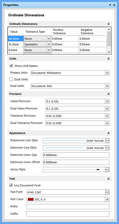
The Ordinate Dimensions mode of the Properties panel
- Ordinate Dimensions – a table arrangement showing the Value and Tolerance settings for the individual dimensions that make up a set of Ordinate Dimensions.
- Value – a list of measured dimensions that have been placed in the ordinate set, shown in the base document units.
- Tolerance Type – use the drop-down to select the tolerance type (None, Symmetric, Bilateral, or Limit) for the individual dimension represented by its table row.
- Positive/Negative Tolerance – enter the desired positive and negative tolerance value for the dimension. These fields are not active if None is selected for the Tolerance Type.
- Units – set the Units types for this object instance.
- Show Unit Names – enable to show unit names, for example,
10.1mmas opposed to just10.1. - Dual Units – check to enable two measurements for each dimension, with one set to show the Primary Units type setting and the other showing the Dual Units type setting.
- Show Unit Names – enable to show unit names, for example,
- Precision
- Value Precision – the measured dimension in the base document units. Use the drop-down to select the precision value from the list.
- Dual Value Precision – the measured dimension in the base document units set for the alternative value. Use the drop-down to select the precision value from the list.
- Tolerance Precision – use the drop-down to select the tolerance precision value from the list.
- Dual Tolerance Precision – use the drop-down to select the tolerance precision value from the list, for the alternative unit measurement.
- Appearance – use the following options to change the line width size, style and color, and arrow graphic style.
- Dimension Line Style – use to open the Line Style dialog to select the dimension line style.
- Extension Line Style – use to open the Line Style dialog to select the extension line style.
- Extension Lines Gap – enter the value desired for extension lines gaps.
- Extension Lines Offset – enter the value for extension lines offsets.
- Arrow Style – use to open the Arrow Style dialog to select the style for arrows.
- Dimension Line Style – use
- Text
- Use Document Font – enable to force the placed view to adopt the font style defined in the global Draftsman Document Options dialog.
- Text Font – use to open the Font dialog to select the desired font. This option is available only when Use Document Font is not checked.
- Text Color – use the drop-down to select the color for text.
- Prefix – use to add prefix text to the dimension text. Enter the desired prefix, if necessary.
- Suffix – use to add suffix text to the dimension text. Enter the desired suffix, if necessary.
Line

The Line mode of the Properties panel
- Geometry
- Start Point X – enter the line start point for the X axis.
- Start Point Y – enter the line start point for the Y axis.
- End Point X – enter the line end point for the X axis.
- End Point Y – enter the line end point for the Y axis.
- Line Style
- Style – use to open the Line Style dialog to select the line style.
- Style – use
Rectangle

The Rectangle mode of the Properties panel
- Geometry
- Start Point X – enter the rectangle start point for the X axis.
- Start Point Y – enter the reactange start point for the Y axis.
- Width – enter the rectangle width.
- Height – enter the rectangle height.
- Style – sets the line weight/style.
- Style – use to open the Line Style dialog to select the style.
- Style – use
Circle

The Circle mode of the Properties panel
- Geometry
- Center Point X – enter the center point for the X axis.
- Center Point Y – enter the center point for the Y axis.
- Radius – enter the radius.
- Styles – sets the line weight/style.
- Line Style – use to open the Line Style dialog to select the line style.
- Line Style – use
Text

The Text mode of the Properties panel
- Geometry
- Start Point X – enter the text box start point for the X axis.
- Start Point Y – enter the text box start point for the Y axis.
- Width – enter the text box width.
- Height – enter the box height.
- Rotation – use the drop-down to select the text rotation: 0º, 90º, 180º, or 270º.
- Text
- Use Document Font – enable to force the placed view to adopt the font style defined in the global Draftsman Document Options dialog.
- Font – use to open the Font dialog to select the desired font. This option is available only when Use Document Font is not checked.
- Color – use the drop-down to select the color for text.
- Text – enter the default new text in the text box. Use
 to open the Document Parameters dialog in which you can view the available parameters.
 - Clip Text To Bounds – enable to constrain the text within the text box bounds (enable word wrap).
- Align
- Horizontal – use the drop-down to align the text horizontally: Left, Center, or Right.
- Vertical – use the drop-down to align the text vertically: Top, Center, or Bottom.
Graphic

The Graphic mode of the Properties panel
- Geometry
- Start Point X – enter the X axis starting point for the graphic image.
- Start Point Y – enter the Y axis starting point for the graphic image.
- Width – enter the image width.
- Height – enter the image height.
- Rotation – use the drop-down to select the image graphic rotation: 0º, 90º, 180º, or 270º.
- Image
- Maintain Aspect Ratio – enable to maintain the image width/height ratio.
Note
Note Item lists can be placed as free text entries in any location. The entries can be referenced by Callouts and configured and edited in the Note mode.

The Note mode of the Properties panel
- Size
- Width – enter the desired width.
- Title – sets the name, its font/color and visibility settings. System or custom parameters can be used in the title.
- Show Title – enable to show the title.
- Title – enter the title name.
- Use Document Font – enable to force the placed view to adopt the font style defined in the global Draftsman Document Options dialog.
- Title Font – use to open the Font dialog to select the desired font. This option is available only when Use Document Font is not checked.
- Title Color – use the drop-down to select the title color.
- Elements
- Use Document Font – enable to force the placed view to adopt the font style defined in the global Draftsman Document Options dialog.
- Element Font – use to open the Font dialog to select the desired font. This option is available only when Use Document Font is not checked.
- Element Color – use the drop-down to select the element color.
- Horizontal Spacing – enter the desired value for horizontal spacing.
- Vertical Spacing – enter the desired value for vertical spacing.
- Selected Element
- Note Item Number – displays the item number of the note.
- Border – use the drop-down to select the border type: None, Square, Circle, or Triangle.
- Note description – click in the textbox to enter/edit the note text. Click to open the Document Parameters dialog to select an existing (system) parameter or custom parameter.
- Right-click Menu
- Undo – select to undo the last edit.
- Cut – select to delete the selected data.
- Copy – select to copy the selected data.
- Paste – select to paste the last copied data.
- Delete – select to delete the selected data.
- Select All – select to select all data in the current region.
- Right-click Menu
- Add – click to add a new element. The Border type appears initially as None. Use the drop-down to define the border type: None, Square, Circle, or Triangle. The Text region appears initially as New Element. Click in the region and enter new text to edit.
- Up – click to move the selected element up on the list.
- Down – click to move the selected element down on the list.
- Delete – click to delete the selected element.