
Component Management
This document is no longer available beyond version 4.0. Information can now be found here: A Quick Guide to Component Management with a Workspace Connected to Altium Designer for version 22

Altium Designer, with its unified design approach, has traditionally used a component model that extends across all aspects of the electronics design process. However, to seamlessly fit the process of electronics design into the encapsulating product development process as a whole, this model needed to evolve - extending to cover other aspects including other design processes (in particular MCAD and Industrial Design), as well as business processes (such as procurement and manufacturing) that intersect with the product development process.
This evolved object model is known as the Unified Component Model.
Under this modeling paradigm, the design component, as seen by the designer, is separated from the Manufacturer and/or Vendor parts. This information is not defined as part of the component. Instead, Part Choices are used to map the design component to one or more Manufacturer Parts, listed in a Part Catalog, which in turn can be mapped to one or more Vendor parts, allowing the designer to state up-front, what real parts can be used for any given design component used in a design.
These components, along with their part choices, are stored in Altium Concord Pro. A component is stored as a series of revisions of a uniquely-identifiable Component Item. Each revision is lifecycle-managed, providing collections of certified components, authorized to be re-instantiated into new design projects, manufactured into prototypes, or used for production runs. In short, a catalog of components implemented through server-based 'libraries'.
The Component Editor
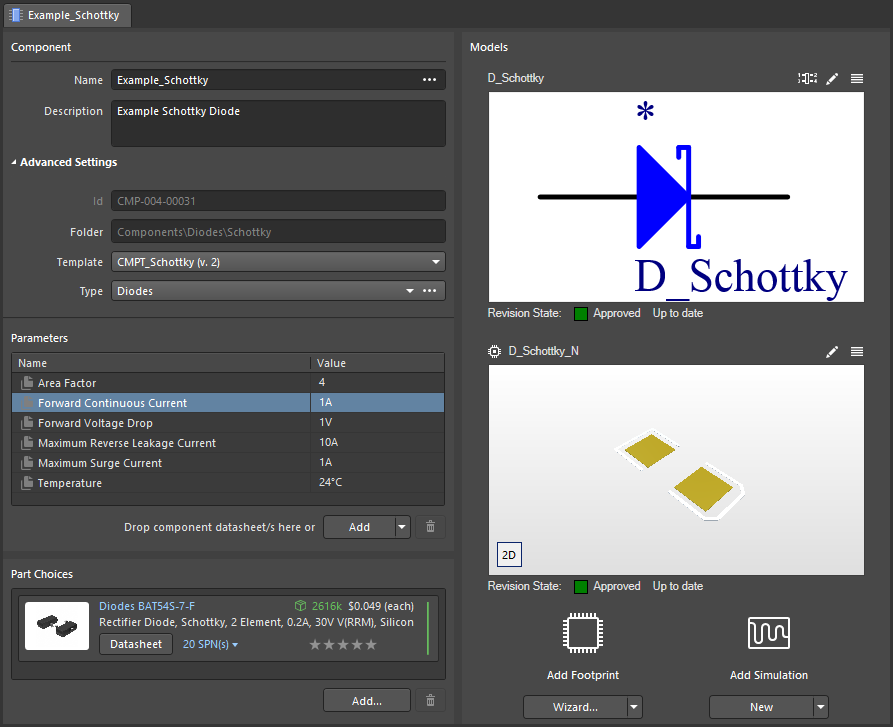
A component is defined/edited using the Component Editor. This editor provides two different modes of operation:
- Single Component Editing mode - provides a streamlined interface when defining/editing a single component. This is the default mode when creating a new Component Item, or editing a single revision of an existing Component Item.
- Batch Component Editing mode - provides the interface for defining/editing multiple components. You can access this mode by choosing the Tools » Switch to Batch Editor command, from the Component Editor's main menus. This mode is also accessed if you have selected multiple Component Item revisions for editing, from the Explorer panel. Each component definition will have a common set of parameters and links to required domain models. Batch editing comes into its own where it makes sense to manage components as a set, such as a set of chip resistors for example.
Managed Domain Models
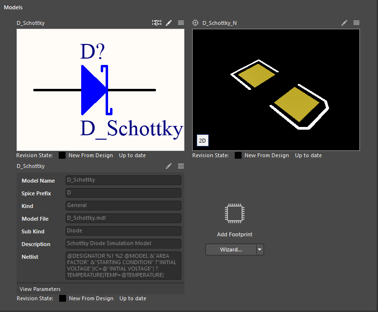
From a designer's perspective, a managed component gathers together all information needed to represent that component across all design domains, within a single entity. It could therefore be thought of as a container in this respect. A 'bucket' into which all domain models and parametric information is stored.
In terms of its representation in the various domains, a managed component doesn't contain the domain models themselves, but rather links to the relevant model Items that are also in a managed content server. These links - to Symbol, Footprint and Simulation Model Items - are specified as part of the component.
Use the following links to take a look at the various domain models that can be stored and managed in Concord Pro:
Component Templates

Helping to streamline the creation of your managed components, Altium Designer, in conjunction with Altium Concord Pro, supports creating and defining Component Templates. Just as a schematic template can be used to predefine information on schematic sheets that reference it, a component template is referenced by a managed component, and provides predefined settings for use when defining that component.
In particular, component templates have been developed with parametric information firmly in mind, allowing you define, in a single location, a 'bucket set' of parameters that will be made available to the referencing component. Through the template, you can control which of those parameters are to be made visible, fill-in default values, and even mark those parameters that are required as mandatory. In addition, you can also force the use of parameters, marking them as required. Validation checks are in-place at the time of component release, to ensure compliance.
The Component Template Editor provides the ability to define explicit data types for component parameters defined within a component template (*.CMPT). In addition, these data types are unit-aware, with a range of popular unit prefixes supported. As such, you can enter a parameter's value using a range of formats - such as 2.2k, 2k2, 4M, 2.5GHz - with Concord Pro engineered with the requisite smarts to recognize the numerical value behind those entries.
This feature of a component template facilitates targeted searching through the Server's Advanced Search facility - a facility that not only allows you to search by component type, but allows you to search smarter, with range searches. Using the power of unit-aware component parameters, you can quickly define a search, for example, to find all capacitors with a capacitance between 47uF and 220uF.
Adding Datasheets
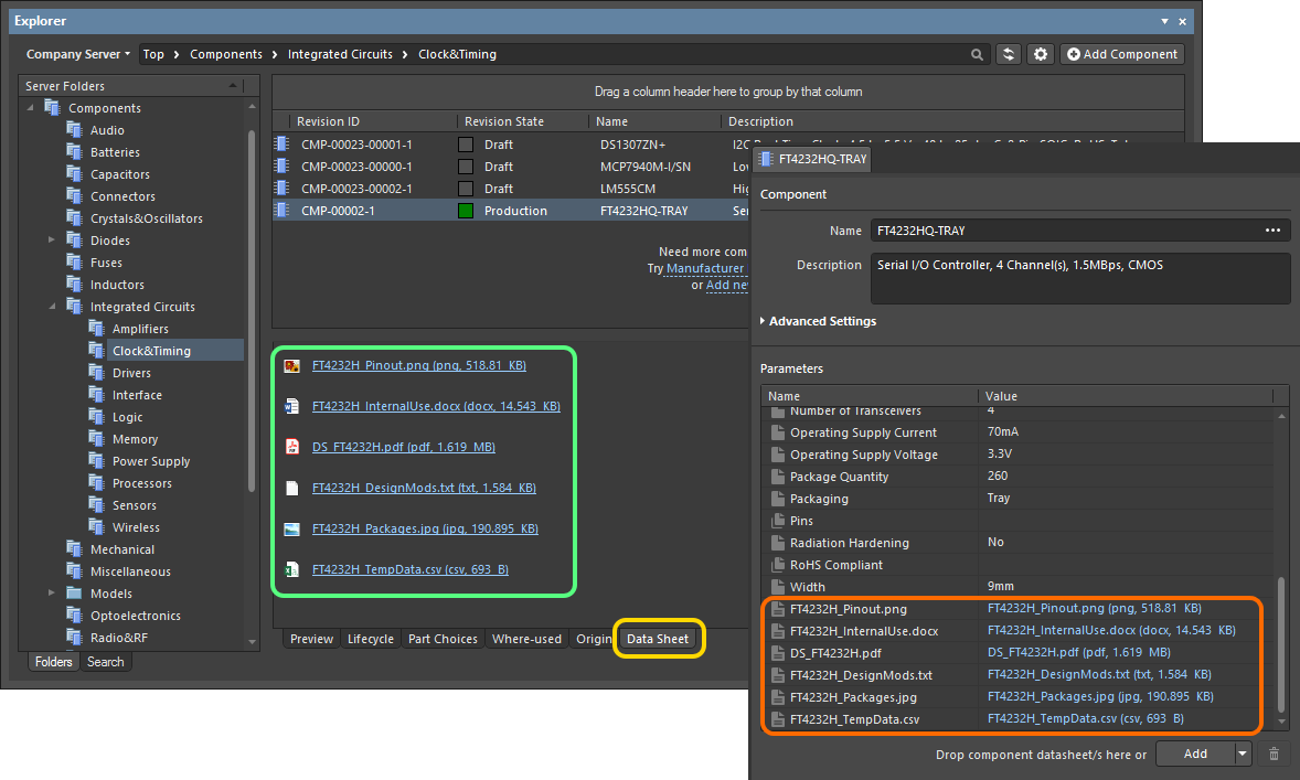
Altium Designer, in conjunction with Altium Concord Pro caters for the ability to store component datasheets within that server and, in doing so, link them to target managed components. This allows you to more fully describe and support a component, in a centralized fashion, while reducing the reliance on external storage mediums (shared network drives for example). Storing datasheets next to the very components that need to reference them also means you no longer need to have a live internet connection, to consult a reference document that can often, and frustratingly, disappear without warning at the whim of the hosting website!
One or more datasheets can be attached (uploaded) to a component - essentially creating a link between the component and the datasheet(s) - when creating/editing that component through the Component Editor.
For an existing component in your Concord Pro instance, one or more datasheets can be attached (uploaded) through the Explorer panel. While browsing the required component, switch to its Data Sheet aspect view.
Part Choices
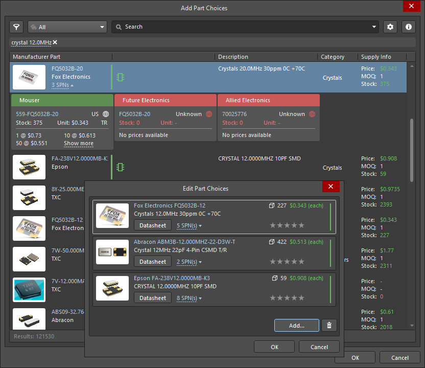
In the Supply Chain Area, a procurement specialist often does not know what a particular component in the design represents. What is required, is an indication of what needs to be procured - which physically-manufactured components can be used to implement that design component. The best person to indicate which real-world components can be validly used to implement the design-level components would be the designer. As part of the Unified Component modeling paradigm, Altium caters for exactly that through the concept of making Part Choices.
Part Choices essentially create the mapping from a component in your Altium Concord Pro instance, to nominated Manufacturer Parts in that instance's local Part Catalog. In other words, Part Choices specify the 'allowed' manufacturer parts that can be used to implement that component on the assembled board. The actual supply chain intelligence - comprising Manufacturer (and part number), Supplier (and part number), Description, Pricing and Availability - is sourced from Altium Concord Pro's local Part Catalog and the relevant Part Source.
The designer can feel truly empowered by being able to specify Manufacturer Parts that are truly interchangeable at manufacturing time in the context of any usage of that component in their design - the very essence of true part equivalency. And it is this intelligent mapping of a component, that turns the humble managed component into a truly Unified Component. The unified nature of a managed component, through the chosen part choices made for it, ultimately creates a link from that component, all the way through chosen Manufacturer Part(s), and on to the Vendor (Supplier) Parts that each itself references. From the designer's perspective, the component is hooked directly into the supply chain.
Real-time data is made available - fed back from the relevant parts database - to let the designer know the current costing and availability of the chosen parts, and from all enabled Vendors that sell those chosen parts (as defined in the local Part Catalog). And the procurement specialist can also keep abreast of supply-chain information, as it is made available in Concord Pro for each component therein.
A part is no longer available or has suddenly become cost-ineffective? No matter, provision is made for real-time updates to be sent back to the Design Area as soon as a change occurs. With this vital 'heads-up', the designer can take that choice of part out of the associated list of Part Choices for that component and essentially 'off the radar'. And at any time additional new, truly equivalent parts can be added to the list, should something more appropriate, available, and cost-effective come along.
Part Source Configuration

Each Altium Concord Pro instance has its own dedicated Part Catalog. This is a managed local part catalog database, dedicated to the management and tracking of manufacturer parts and their associated supplier parts. The catalog is installed as a service (Part Catalog Service), provided through the Altium Concord Pro platform and works only with Altium Concord Pro.
The local Part Catalog stores items representative of actual Manufacturer Parts, along with one or more items representative of Supplier Parts - the incarnations of those Manufacturer Parts, as sold by the Suppliers/Vendors. Each Supplier Part is a reference to an item in a parts database - either the aggregate parts database of the Altium Parts Provider (which itself interfaces to, and gathers the parts from, enabled Suppliers) or a linked local parts database (ODBC-based).
Which Supplier Databases are actually used - a list of Approved Suppliers - is managed by Altium Concord Pro, through the Part Providers page of its browser interface. This facilitates centralized supply chain management, with designers across the entire organization using the same approved list of Suppliers, with which to source supply chain intelligence for parts used in their designs.
Migrating Existing Libraries
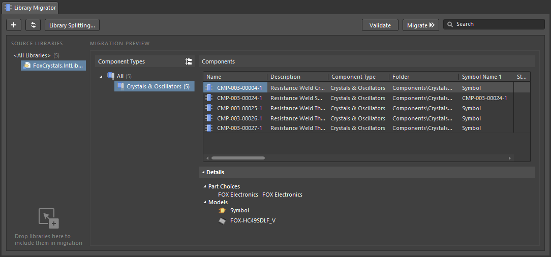
Altium Designer provides a streamlined, simple process to quickly migrate your existing libraries to Altium Concord Pro. The GUI to this process - the Library Migrator - presents an intuitive flow that takes initial selected libraries, and migrates them to your Concord Pro instance. Catering for all types of libraries relating to older component management methodologies - SCHLIB, PCBLIB, INTLIB, DBLIB, SVNDBLIB - the Library Migrator is the perfect solution to quickly building your company's set of managed components, and the many benefits that such components enjoy (high-integrity, lifecycle management, centralized storage and management, where-used functionality, ease of design resuse).
The Library Migrator offers a minimalist Simple interface mode where the selected file-based component libraries are migrated to managed server components through a single step, while the migrator automatically takes care of type classification, the target source folder, parameter inclusion and value type, and the transfer of all relevant data. The interface is also available in an Advanced mode that provides a full preview of the proposed library migration, and access to its related data and settings. And while the migration is a single-click process by default, the migrator also offers advanced configuration options through the Properties panel for enhanced control over exactly how that migration is performed.
All information that is present in an original source library is migrated to the server-based managed components, including all referenced domain models (schematic symbols, PCB footprints, Simulation Models), parametric information, assigned part choices, datasheet files, etc . Component Templates are also created where necessary, and may then be refined and used for subsequent library migrations. If your original components have multiple PCB footprints defined, the Library Migrator will bring those models across and keep the current default footprint. And if you only work with PCB libraries – your only concern is PCB layout – then the Library Migrator supports migration of just those libraries, or it can be switched to a models only migration mode where specified models types are migrated from Integrated or Database libraries. Libraries that include multiple component types (monolithic libraries) are automatically detected and processed as well.