
Linking ECAD and MCAD Design Components
Parent page: ECAD-MCAD CoDesign
How Components are Passed Back and Forth Between ECAD and MCAD
CoDesigner's default behavior is to transfer the components back and forth between MCAD and ECAD through your Altium Workspace as Parasolid models.
For many components this will be adequate, representing the component accurately in both design spaces. However, in some companies this might not be enough - they may require both the MCAD and the ECAD engineers to use native component models designed for their software. Not only will a true, tool-specific component model accurately represent the component in that design space, it can also be important for accurate output generation; such as fabrication files and the final Bill of Materials.
All of the MCAD and ECAD design software tools have their own approach to how component models can be stored. To allow native components to be used in each design domain, CoDesigner supports methods of linking the components between the domains. Before exploring native component model linking, it is worth understanding the default approach to transferring component models, and how the linked models are named.
The Default Component Transfer Mechanism
CoDesigner's default behavior is to transfer the component models back and forth between MCAD and ECAD as Parasolid models.
If the model originates in ECAD as:
- A 3D model that is part of an ECAD component - it is pushed to MCAD as a part. Changes to its location in MCAD are then transferred back to ECAD.
- A 3D model that is not part of an ECAD component - it is not pushed to MCAD.
If the model originates in MCAD as:
- An MCAD Part - it is pushed to ECAD as an ECAD 3D Body object and is identified by CoDesigner during Pull as a FreeBody. Any change to the location of an ECAD FreeBody (3D Body object) is not transferred back to MCAD.
Synchronizing Changes to the Component Locations
To be able to synchronize component location changes, the MCAD part must exist as a component in ECAD.
- This occurs automatically if the component originates in ECAD.
- If the part originates in MCAD, the default behavior is to Pull the part into ECAD as a FreeBody, so location changes will not synchronize. You will need to either replace the FreeBody with an ECAD component in ECAD, or link from the MCAD Component to the ECAD Component so that it is automatically replaced during Pull into ECAD.
- ECAD components can include items such as fasteners and heatsinks. If the BOM is being generated in ECAD, include an ECAD symbol as part of the ECAD component so that it can be included in the BOM.
How the Component Models are Named
As CoDesigner converts each component to a Parasolid model, they are named using the following scheme:
<Footprint Name>_<ComponentDesignItemID>_<ItemRevision>
The following special characters, along with other control symbols, are replaced with an underscore (_):
\, /, :, %, [whitespace], |, [, ], *, ", ', \t
 The default naming scheme used for component models.
Controlling the Naming of Component Models
From CoDesigner 2.6 onward, you can configure the component model naming scheme in the Workspace, as detailed below.
CoDesigner supports four options for controlling how component models are named, during their initial transfer from ECAD to MCAD:
<FootprintName>, then<ComponentID>(the default option, and how it worked before this control was added)<ComponentID>, then<FootprintName><FootprintName>, then<CustomComponentProperty><CustomComponentProperty>, then<FootprintName>
Configure the Naming of component models options in the MCAD CoDesigner section of the Workspace Settings.
, define the parameter name.") Select the Naming option and if it includes a Custom Component Property (parameter), define the parameter name.
Select the Naming option and if it includes a Custom Component Property (parameter), define the parameter name.
These options simplify the interaction with the components in MCAD, allowing the MCAD engineer to add meaningful information such as part numbers into the Component ID, or the ECAD engineer can add a Custom Component Property in the ECAD component library.
 The MCAD model is named based on the naming option configured in the Workspace.
Configuring the MCAD-to-ECAD and ECAD-to-MCAD Native Component Linking
The default behavior when a design is Pushed from either the MCAD or ECAD domains, CoDesigner converts the components to Parasolid format models and stores them in the connected Workspace. When that design is Pulled, CoDesigner builds a model of each component in the format required by the target tool.
This approach gives an accurate representation of each component in both the ECAD and the MCAD design spaces. The disadvantage of this approach is that the model does not fully represent the component as it needs to be represented in that tool. For example, when a design is Pulled into ECAD the component will not include the pads, silkscreen, and other entities typically included in a PCB component. Nor will it be linked to a schematic symbol, or into the supply chain. A better approach is to be able to link from the model/component used on one side, to an equivalent, native model/component on the other side.
To manage the requirement for each design tool to be able to use native components, CoDesigner supports linking between the MCAD and ECAD components. The links are defined in the Workspace, which acts as a bridge between the ECAD and domains. CoDesigner uses these settings to establish MCAD-to-ECAD and ECAD-to-MCAD component links, so that the source model/component can be replaced by a native model/component in the target domain, when the board is Pulled.
 This image shows the component linkage settings in an Altium 365 Workspace, the settings are the same in an on-site Workspace.
► Learn more about how to log in to configure the settings for CoDesign
Requirements for the MCAD and ECAD Models
Working with native components on each side means that there are different component models in MCAD and ECAD. For this to work, the 3D models must be geometrically the same on both the MCAD and ECAD sides.
Geometrically the same means:
- The location of the origin within the MCAD model and the ECAD model is the same.
- The orientation of the models’ XYZ axes are the same (note that the XYZ axes can be oriented in any direction).
- The model extents should be approximately the same (not exactly the same, but close).
Notes:
- Top side / bottom side placement is defined according to the location of the model’s origin relative to the board. It is strongly recommended not to use MCAD models that have the origin located below the MCAD plane through the middle of the board.
- Make sure that each model consists of a single part and not an assembly, and does not contain more than one origin. If you have any doubts - check the models on both sides after import.
- The format of the models can be different in MCAD and ECAD (for example, a Creo part used in PTC Creo, and a STEP model used in your Altium design software).
- The level of detail in the models can be different, for example, a precise model in MCAD and a simplified model in ECAD. Note that if a simplified model is used, for example, a rectangular prism, it must have the same bounds and origin as the precise model, for model placement to work correctly.
Guidelines for Orienting the 3D Model
It is common for MCAD component models to have an origin and use an orientation that is not ideal for placement in ECAD. This will not be an issue as long as the MCAD and ECAD models have the same origin and the same orientation of their axes.
The images below show the same model open in Creo, and then in the Altium PCB library editor. This component model was designed with the origin in the center of the front vertical plane (when the component is oriented for mounting on a PCB).
 The origin of the MCAD part is the center of the front vertical plane, as viewed.
When it is first placed in the PCB library editor, the model will be oriented as shown below.
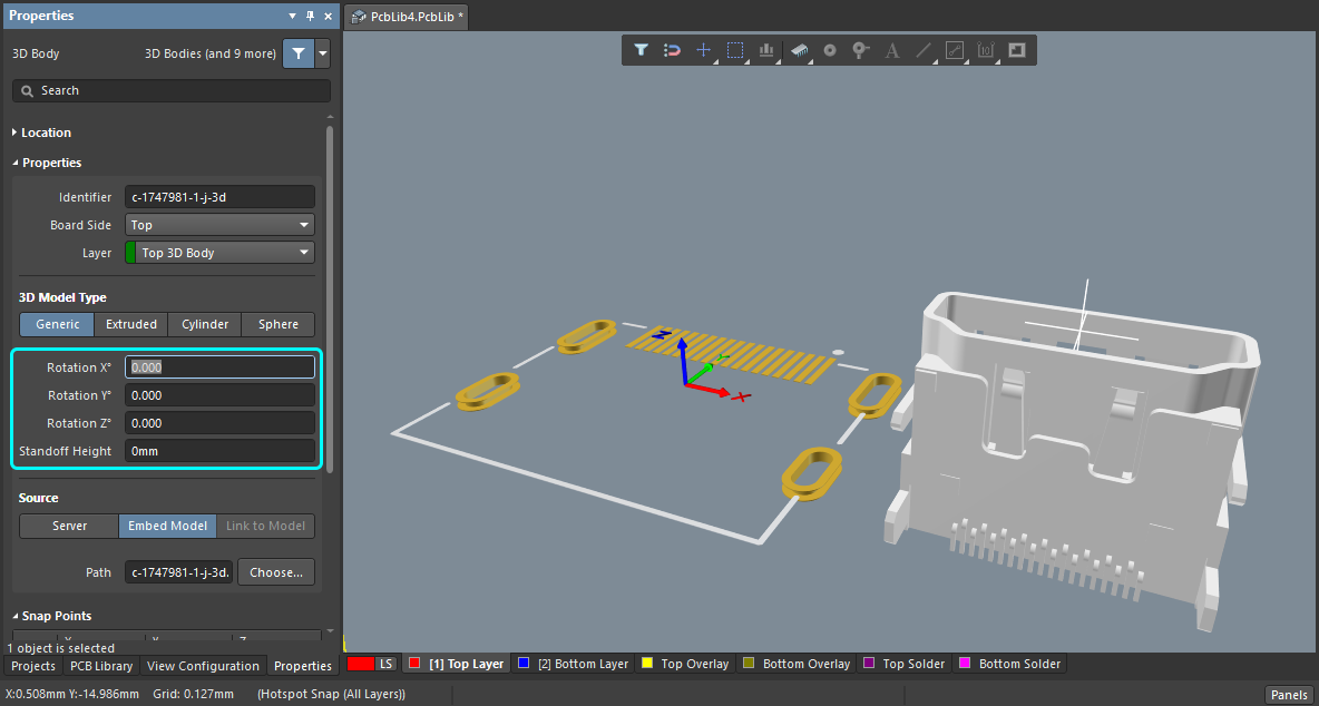
It can then be re-oriented by selecting it and adjusting the Orientation settings in the Properties panel.
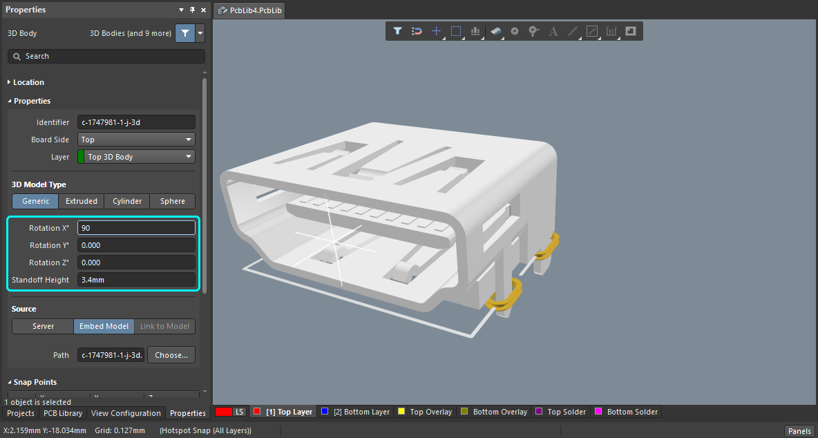
CoDesigner manages these orientation changes correctly when the design is pushed and pulled between MCAD and ECAD, as long as the MCAD and ECAD models share the same origin and orientation of axes.
► Learn more about Orienting and Positioning a 3D Model in Altium's design software
How 3D Models are Handled in Altium's Design Software
You might have noticed that the Properties panel shown above is titled 3D Body, and the 3D Model Type is Generic. Altium's PCB editor includes basic 3D shapes, referred to as 3D Body objects, that can be placed and sized to create a representation of the physical component. A 3D Body object can have a shape of type: Extruded, Cylinder and Sphere.
A 3D Body Object can also be used as a container to hold a true 3D model, by setting the 3D Model Type to Generic. When the type is set to Generic, 3D models of type: STEP (*.Step and *.Stp), Parasolid (*.x_t and *.x_b) and SOLIDWORKS Parts File (*.SldPrt) can be loaded into a 3D Body object.
Using an MCAD 3D Model in ECAD
3D models can be sourced from a variety of places, including component manufacturer websites and 3rd party websites, as detailed below. Complex component shapes are supported, and if required, additional snap points can be defined in the PCB library editor.
 A complex 3D model in Altium's PCB library editor, positioned on the PCB footprint.
► Learn more about Working with 3D Bodies
► Learn more about Creating a Workspace Component
Extracting a 3D Model from ECAD to use in MCAD
Many of the components available in Altium's design software already include a true 3D model. These can be extracted from the ECAD component, if required, to use in your MCAD software.
To do this for a managed component:
- Locate the required component in the Components panel.
- Right-click on the component and select Edit from the context menu.
- The component will open for editing, click the edit icon above the footprint to open it for editing.
- The footprint will open for editing, select the Tools » Extract 3D Models command to extract the 3D model.
- The Generate 3D Model files from PCB Libraries dialog will open, configure your preferred destination option and click OK to extract the model.
The video below demonstrates this process.
3D models can be extracted from Altium components if required.
Resolving Problematic Models
Each ECAD and MCAD tool has its own approach to model conversion, offering different levels of support for importing and converting a model that has issues with inconsistencies or inaccuracies in the model description. To help in this situation CoDesigner transfers single-body models in Parasolid Text format directly from ECAD to MCAD, without transformation and without converting (which could sometimes result in the corruption of a model).
If a model is causing problems during a Push-Pull between ECAD and MCAD, extract it from the ECAD component (as described above), import it into your MCAD software, and save it out as Parasolid Text (confirming that it opens correctly in MCAD), then import it back into the ECAD component.
Linking from the MCAD Components to the ECAD Components
The typical design flow is for the components to be placed in ECAD. However, it is also desirable for the mechanical engineer to be able to place key components, such as connectors, directly in MCAD as part of the initial board definition cycle. When a component is placed in MCAD it is a 3D model, when that model is pushed to ECAD the default behavior is for CoDesigner to transfer it as a free 3D body.
This default behavior can be overridden by enabling and configuring the component recognition features in the shared Workspace. When this is done, it means that each MCAD 3D model can be linked to an equivalent ECAD component. When the board is pulled into ECAD, instead of the MCAD 3D model being used, it is replaced by an instance of the fully-defined ECAD component footprint, complete with 3D model.
 Configure the properties that identify the MCAD-to-ECAD component linkage.
In the example image above, the linkage is from the MCAD parameter called PARTNUM - to the ECAD parameter called PartNumber. When the value of the MCAD PARTNUM parameter matches the value of the ECAD parameter PartNumber, a link is established and the ECAD component is placed instead of the 3D model pushed from MCAD.
CoDesigner can link the MCAD components to the equivalent ECAD components in the following ways:
| From the MCAD Model | To the ECAD Component | Notes about this combination |
|---|---|---|
| In the MCAD model property used for mapping and recognition field: | In the ECAD component parameter used for mapping and recognition field: | Enable the Recognize models placed in MCAD and use true electrical components in ECAD instead option, configure the options as detailed below, and click Save. |
Enter the Custom Parameter Name |
Enter the Custom Parameter Name |
Add a Custom Parameter to both the MCAD model and the ECAD component, with the same parameter value. |
Select MCAD model name from the dropdown |
Enter the Custom Parameter Name |
Add a custom parameter to the ECAD component, whose value is the filename of the MCAD model. |
HOLDING BAY FOR FULL LINKAGE TABLE - slated for addition in an upcoming release
| From the MCAD Model | To the ECAD Component | Notes about this combination |
|---|---|---|
| In the MCAD model property used for mapping and recognition field: | In the ECAD component parameter used for mapping and recognition field: | Enable the Recognize models placed in MCAD and use true electrical components in ECAD instead option, configure the options as detailed below, and click Save. |
Enter the Custom Parameter Name |
Enter the Custom Parameter Name |
Add a custom parameter to both the MCAD model and the ECAD component, with the same parameter value. |
Enter the Custom Parameter Name |
Select Component name from the dropdown |
Add a custom parameter to the MCAD model, whose value is the name of the ECAD component. |
Enter the Custom Parameter Name |
HRID | Add a custom parameter to the MCAD model, whose value is the ECAD component's Item Number????. |
Select MCAD model name from the dropdown |
Enter the Custom Parameter Name |
Add a custom parameter to the ECAD component whose value is the filename of the MCAD model. |
Select MCAD model name from the dropdown |
Select Component name from the dropdown |
The MCAD filename must match the ECAD component name. |
Select MCAD model name from the dropdown |
HRID | The MCAD filename must match the ECAD component's Item Number???. |
Where the ECAD Components are Stored
For this MCAD to ECAD component linkage system to work, CoDesigner needs to know where to search for the ECAD component with a matching parameter. To use native component linking from MCAD to ECAD, the ECAD components must be managed components stored in a Workspace. CoDesigner will search for the components in the same Workspace that the board design is being transferred through.
 When the Recognize models placed in MCAD feature is being used, CoDesigner will search the Workspace for an ECAD component with the matching parameter/value.
Synchronizing Components from MCAD to ECAD
When the PCB is pushed from MCAD and then pulled into ECAD, CoDesigner:
- Checks for a match between each MCAD component and the existing ECAD components. Components are matched first by the defined property/parameter pair, then by reference designator. For a match, CoDesigner will suggest making changes to the location of components and to their properties, if necessary.
- For each component coming from MCAD that is not present in the ECAD domain, check if the Recognize models placed in MCAD and use true electrical components in ECAD instead, option is enabled in the Workspace.
- If enabled, check the MCAD model property used for mapping and recognition setting in the Workspace to see which MCAD component parameter to use, then read the value of that parameter from the MCAD component (this is the value used to find a match on the ECAD side).
- Then check the Workspace for the ECAD component parameter used for mapping and recognition setting for the name of the parameter to use on the ECAD side.
- Then search the Workspace for an ECAD component that matches that parameter/value.
- If a component with the matching parameter/value is found in the Workspace, place that native ECAD component on the PCB. These components are flagged as recognized in the CoDesigner panel.
- CoDesigner then does an additional check to see if this component is already present on the ECAD schematic, and if it is, assigns the schematic designator to the placed PCB component. Note that the PCB editor's Project » Component Linking command must be run to establish the schematic-to-PCB component linking.
- If the component is not found in the Workspace, place the 3D model that came from MCAD. These are flagged as FreeBody in the CoDesigner panel. As a FreeBody (3D Model), these can be edited and replaced in ECAD with an alternate 3D model, if required.
- If the Recognize models placed in MCAD and use true electrical components in ECAD instead option is not enabled, or if it is enabled but the MCAD component does not include the specified MCAD model property used for mapping and recognition, CoDesigner places the MCAD model with the designator that came from MCAD. These are flagged as Added in the panel.
Example of Synchronizing Components Using Custom Parameters
If a placed MCAD component includes the custom parameter defined in the MCAD model property used for mapping and recognition field, CoDesigner will search for that component in the ECAD components available in the Workspace.
In the example below, the Workspace settings are mapping the MCAD part parameter, PARTNUM, to the ECAD component parameter, PartNumber. A match is detected when these parameters share the same value.
 The MCAD part uses the parameter PARTNUM, and the ECAD component uses the parameter PartNumber.
The image below shows the PARTNUM parameter has been added to the MCAD part, for this part it has a value of MINI_D-300-0058.
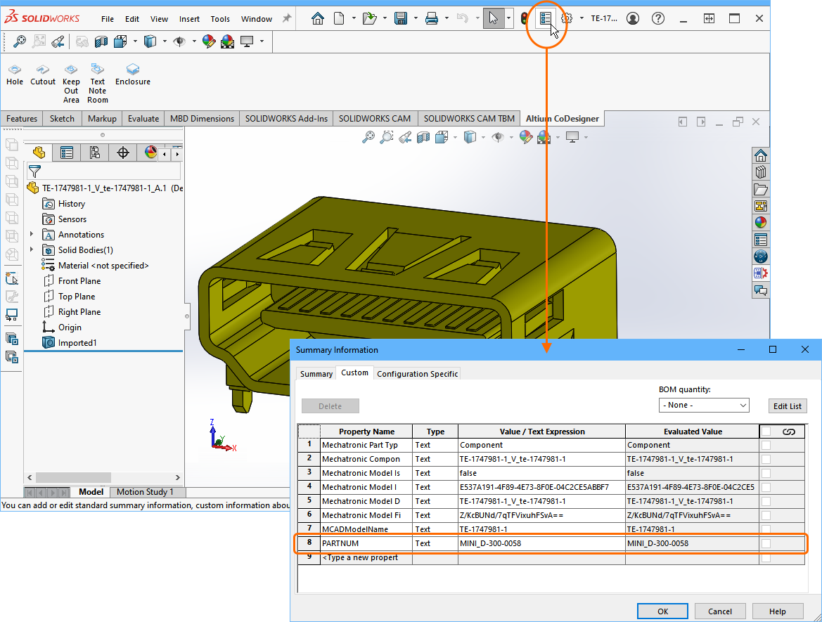
Because the Recognize models placed in MCAD and use true electrical components in ECAD instead option is enabled in the Workspace, the PARTNUM parameter and its value are Pushed to the Workspace as part of the board data.
When a Pull is performed from ECAD, CoDesigner will:
- Detect that the Recognize models placed in MCAD and use true electrical components in ECAD instead option is enabled in the Workspace.
- Check for the PARTNUM parameter in the incoming MCAD 3D component parts and read the PARTNUM parameter's value.
- Search the Workspace components for a component that includes the ECAD PartNumber parameter, with that value.
- If one is found, the ECAD component will be placed instead of loading the Parasolid model included in the board data. The Change list will show it as
New (recognized), as shown below. - CoDesigner then does an additional check to see if this component is present on the ECAD schematic, and if it is, assigns the schematic designator to the placed PCB component. Note that the PCB editor's Project » Component Linking command must be run to establish the schematic-to-PCB component linking.
 When an MCAD property/ECAD parameter match is found, the ECAD component is flagged as recognized.
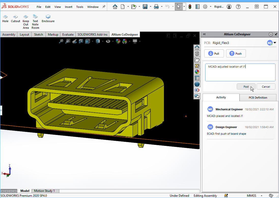
Note that the connector placed from the Workspace is a native Altium component, complete with pads and silkscreen.
 Instead of transferring a model from MCAD, the native component has been placed from the Altium 365 Workspace.
Synchronizing Existing Components
When design changes are pushed from ECAD and pulled into MCAD, CoDesigner matches existing components with components that came from ECAD, suggesting to make changes to the location of components and to their properties, if necessary.
Additionally, CoDesigner identifies the components which were initially placed in MCAD. These components will not be marked by the special attributes set up by CoDesigner, identifying them as ECAD-owned. CoDesigner does not replace such components, the original MCAD model is retained. However, it adds the corresponding ECAD features to the bare board: including holes, silkscreen, and copper (optional).
If an MCAD-owned component is moved/rotated in ECAD, CoDesigner keeps its proper orientation in MCAD (relatively to the board). It even works for MCAD models that have their Z-axis oriented horizontally.
Linking from the ECAD Components to the MCAD Components
MCAD CoDesigner also supports the placement of native components when the PCB is being Pushed from ECAD and Pulled into MCAD. To do this, CoDesigner asks the MCAD software to get the model of the component from the MCAD's data management system (by the model’s name) and then places that component on the MCAD PCB assembly, instead of the model that came from ECAD.
This is achieved by mapping the MCAD model name to an ECAD component parameter (or a footprint parameter for CoDesigner 3.4 or newer). The ECAD parameter that is used to store the MCAD model name is specified in the Workspace that CoDesigner uses to pass the board design back and forth between the MCAD and ECAD design domains.
 Enable and configure the Use models from data management system option, and Save the changes. This image shows a workspace hosted on Altium 365.
To configure the shared parameter/property:
- Log in to your Workspace in your browser. (Learn how to: log into a 365 Workspace; log into a Concord Pro Workspace; log into a NEXUS Server Workspace)
- Open the Admin - Settings page as shown above and select MCAD CoDesigner in the center of the page to configure the property/parameter.
- Check the Use models from data management system on MCAD side when creating PCB Assembly option to enable the feature and be able to define the ECAD parameter.
- Enter the name of the ECAD component parameter used for storing MCAD model name. Note that this value is not case-sensitive.
- Click the Save button to save the change.
Specifying the MCAD Component as an ECAD Footprint Parameter
Introduced in the 3.4 update, CoDesigner also supports taking the name of the MCAD model from an ECAD custom Footprint property, as an alternative to the custom Component parameter. This feature better supports the many-to-many relationships between the components and footprints.

As well as specifying the MCAD model reference as an ECAD component parameter, an ECAD footprint parameter can also be used.
How the Native MCAD Components are Placed in MCAD
If the Use models from data management system on MCAD side option is enabled, CoDesigner in ECAD will include the parameter and parameter value in the board definition pushed to the shared component management system.
 This ECAD component includes the MCADModelName parameter, with a value of nn_DF40_2.
CoDesigner in MCAD will detect this and request that the MCAD software search for the component using the parameter value as the model name, in the connected MCAD Data Management system. The image below gives an example of this in PTC Creo.
 A model with this name is available in the connected Windchill Workspace.
CoDesigner will place the native model in MCAD, instead of the Parasolid format model that has also been stored in the Workspace.
 The native model has been placed on the PCB assembly in Creo.
The ECAD to MCAD component linkage system works by CoDesigner requesting that the MCAD software search for the components that include the ECAD component parameter used for storing MCAD model name parameter (MCADModelName in the example images above). If the component is not available in the MCAD Data Management system, the MCAD software will indicate this and CoDesigner will place the model transferred from ECAD, instead.