
PCB Panel - Polygons Mode

The Polygons mode of the PCB panel
Summary
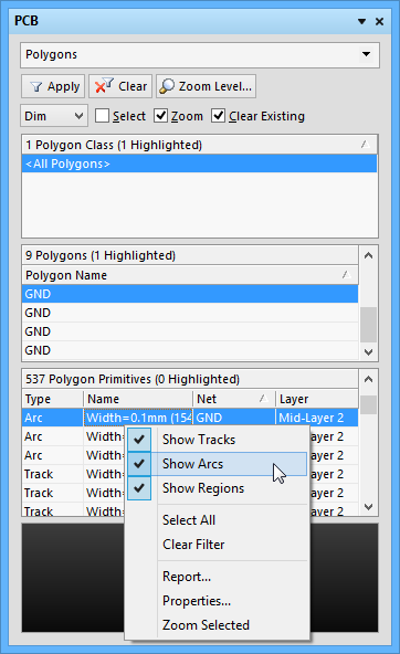
The Polygons mode of the PCB panel can be used to browse polygon classes, individual polygons, and polygon primitives.
The three main list regions of the panel are, in order from the top:
- Polygon Classes.
- Individual Polygons within a class.
- Individual primitives that constitute a Polygon (tracks, arcs and regions).
Panel Access
When the PCB Editor is active, click the PCB button at the bottom-right corner of the workspace then select PCB from the context menu. Alternatively, you can access the panel through the View » Workspace Panels » PCB sub-menu.
Browsing Polygons
For full control and editing of Polygon Classes, open the Object Class Explorer dialog using the Design » Classes menu command. From this dialog, you can view/modify the polygon membership of the class, rename it, or add additional classes.
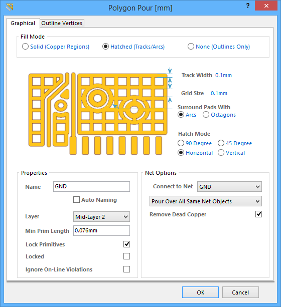
In the PCB panel, right-clicking on a polygon entry then selecting Properties (or double-clicking on the entry) will open the Polygon Pour dialog, from where you can view/modify the properties as required.
Similarly, right-clicking on a polygon primitive entry and selecting Properties (or double-clicking on the entry directly) will provide access to the relevant properties dialog, from where you can view/modify the properties of the primitive as required.
In the PCB panel's Polygon Primitives region, the display/inclusion of each polygon primitive type is dependent on the setting of corresponding enabling option, accessed from the right-click menu.
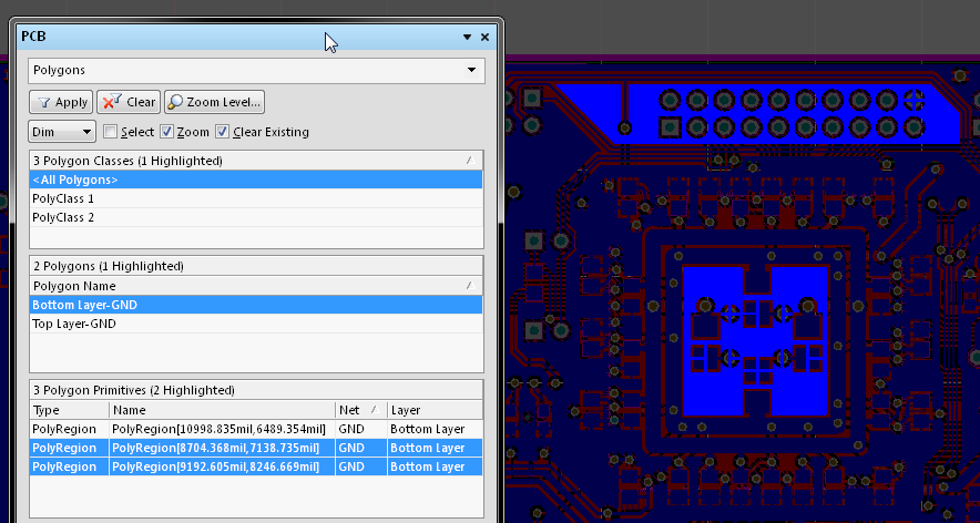
As you click on an entry in the PCB panel's list, a filter will be applied based on that entry, where the visual result of which (in the design editor window) is determined by the enabled highlighting methods (Mask, Dim, Zoom, etc.). Multiple entries can be selected in each region using standard Shift+Click and Ctrl+Click features.