
Document Options (SCH)
The Document Options dialog.
Summary
This dialog allows the designer to define options that are specific to the active schematic document. The dialog is divided over four tabs, collectively providing controls for defining the look and feel of the schematic sheet, enabling and sizing grids, specifying the units of measurement to be used, and any relevant document parameters. It also reflects any default schematic document template that is currently being used for the sheet, with the ability to quickly switch templates.
Access
The Document Options dialog can be accessed from the Schematic Editor in the following ways:
- Right-click and select Options » Document Options from the context menu.
- Select Design » Document Options from the toolbar.
- Select File » Link Sheet to Vault from the toolbar.
Sheet Options Tab
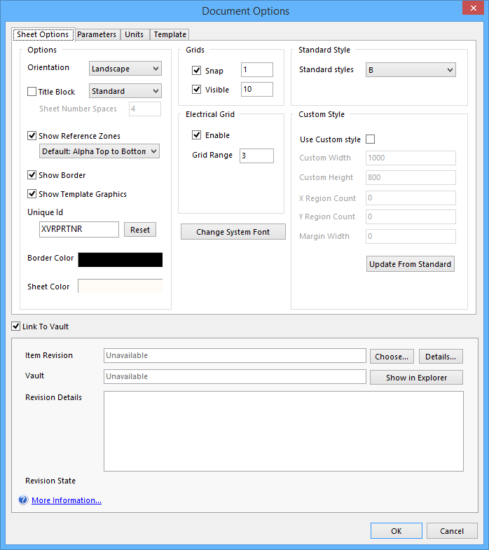
Document Options dialog - Sheet Options tab.
Use the dialog's Sheet Options tab to modify the look and feel of the sheet, as well as its various grids.
Options/Controls
Options
- Orientation - use this field to specify the orientation of the sheet, either Landscape or Portrait.
- Title Block - enable this option to display one of two predefined title blocks on the schematic sheet. Use the associated drop-down field to choose from either a Standard or ANSI title block style.
- Sheet Number Spaces - this option becomes available when choosing to use the Standard predefined title block. Its value determines the space between the text "Sheet" and "of" in the title block. Enter a value between 1 and 16.
- Show Reference Zones - Enable this option to display reference zones around the border of the sheet. Use the associated drop-down field that becomes available to choose from one of the following reference zone order styles:
- Default: Alpha Top to Bottom, Numeric Left to Right - this style labels vertical zones from the top, starting with A, and horizontal zones from the left, starting with 1.
- ASME Y14.1: Alpha Bottom to Top, Numeric Right to Left - this style labels vertical zones from the bottom, starting with A, and horizontal zones from the right, starting with 1.
- Show Border - enable this option to have a border drawn around the perimeter of the sheet. If the option to Show Reference Zones is also enabled, both an inner and outer border will be drawn. The color of the border is determined by the Border Color field.
- Show Template Graphics - enable this option to display any graphics (including title block and company logo) defined on the currently assigned template document.
- Unique Id - the current unique identifier for the document. The Unique ID (UID) is a system generated value that uniquely identifies this current document. A new UID value can be entered directly into this field.
- Reset - click this button to have the system generate a new UID for the document.
- Border Color - click the color sample to change the color of the border around the perimeter of the schematic sheet, using the standard Choose Color dialog.
- Sheet Color - click the color sample to change the color of the schematic sheet, using the standard Choose Color dialog.
Grids
- Snap - use these controls to turn the Snap grid on or off, and to set the grid interval size. The snap grid pulls the cursor to the nearest point on its defined grid, when placing or manipulating objects on the sheet. This grid should be left on at all times except when specifically placing or moving objects that need to be off grid, like text.
- Visible - use these controls to turn the Visible grid on or off, and to set the grid interval size. The visible grid is the grid you see on the sheet, which acts as a visual reference. Typically it is set to be the same as, or a multiple of, the Snap grid.
Electrical Grid
- Enable - enable this option to activate the Electrical grid. The electrical grid supports the Schematic Editor's Guided Wiring feature. When moving an electrical object in the workspace and that object falls within the electrical
grid range of another electrical object that you could connect to, the object you are moving will snap to the fixed object, and a red highlight cross, or Hotspot, will appear. This guides you as to where a valid connection can be made.
- Grid Range - use this field to determine the proximity two electrical objects can be, before one snaps to a valid electrical hotspot on the other. The electrical grid should be set slightly lower than the current Snap grid or else it becomes difficult to position electrical objects one Snap grid apart.
Standard Style
- Standard Styles - use this field to choose from a range of standard sheet styles. The following styles (featuring both metric and imperial sizes) are available: A4, A3, A2, A1, A0, A, B, C, D, E, Letter, Legal, Tabloid.
Custom Style
- Use Custom style - enable this option to define a custom sheet style, with the following properties:
- Custom Width - use this field to specify the width required for the custom sheet.
- Custom Height - use this field to specify the height required for the custom sheet.
- X Region Count - use this field to determine the number of regions, or reference zones, that are displayed along the horizontal border of the custom sheet.
- Y Region Count - use this field to determine the number of regions, or reference zones, that are displayed along the vertical border of the custom sheet.
- Margin Width - use this field to specify the width of the border for the custom sheet.
- Update From Standard - with the Use Custom style option disabled, click this button to quickly load settings for the custom sheet from the currently chosen standard style. This is perfect for when you just need to make slight adjustments from a standard style. Just remember to enable the Use Custom style option again, so that you can use the custom sheet, and make changes to settings as required.
- Change System Font - click this button to access the Font dialog, from where the font style can be changed for system text such as pin and port designators or names, and sheet border characters.\
Link To Vault
Check this option to link document options to the Altium Vault or Altium Content Vault. This section is expanded by default.
- Item Revision - The Item Revision is displayed in this field, if available.
- Choose - Click to open the connected Vault and choose an existing Item revision, or create a new one for this document.
- Details - Click to open a Full Item View of the linked Item in the workspace.
- Vault - The target vault is displayed in this field.
- Revision Details - Displays the details of the current document Revision.
- Revision State - Displays the Revision state of current document.
Parameters Tab

Document Options dialog - Parameters tab.
Use the dialog's Parameters tab to manage parameters for the current document. You can also add rule-based parameters. Parameters defined here are treated as special strings, where the parameter Value is automatically linked to the special string when placed on the sheet.
Options/Controls
- Parameters Grid - the main region of the tab lists all of the parameters currently defined for the document, in terms of:
- Name - the name of the parameter. For a rule-type parameter, this entry will be locked as Rule.
- Value - the value of the parameter. For a rule-type parameter, the entry will reflect the rule type, along with a listing of its defined constraints.
- Type - the type of parameter, which determines the valid entries that can be used for its value. Available types are: STRING, BOOLEAN, INTEGER, and FLOAT. For a rule-type parameter, this entry is always STRING.
- Add -click this button to add a new parameter to the list. The Parameter Properties dialog will appear. Use this to define the parameter, especially its Name, Value, and Type.
- Remove - click this button to delete the selected parameter(s) from the list of parameters.
- Edit - click this button to modify the currently selected parameter. The Parameter Properties dialog will appear, with which to do so.
- Add as Rule - click this button to add a new design rule directive parameter to the list. The Parameter Properties dialog will appear, but this time will contain the Edit Rule Values button, which in turn gives access to the Choose Design Rule Type dialog, from where you can choose, and subsequently define, the constraints of the required rule type.
Right-Click Menu
The Parameters Grid right-click menu offers the following commands:
- Selected On - use this command to quickly enable the Visible option for all currently selected parameters in the list.
- Selected Off - use this command to quickly disable the Visible option for all currently selected parameters in the list.
- Add - use this command to add a new standard (non-rule) parameter to the list.
- Remove - use this command to remove the currently selected parameter(s) in the list.
- Edit - use this command to edit the currently selected parameter in the list.
- Select All - use this command to quickly select all parameters in the list.
- Select None - use this command to quickly deselect all parameters in the list.
Units Tab
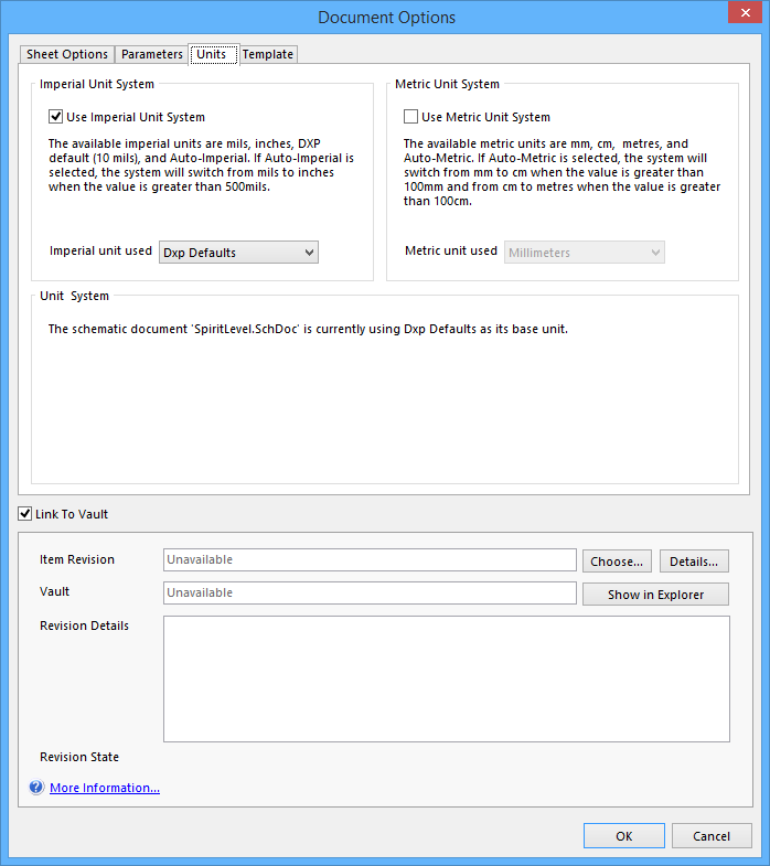
Document Options dialog - Units tab.
Use the dialog's Units tab to specify the units of measurement to be used for the schematic. A range of unit types are available, across both Imperial and Metric systems.
Options/Controls
Imperial Unit System
- Use Imperial Unit System - enable this option to use Imperial units in the schematic.
- Imperial unit used - use the drop-down list associated to this field to choose the type of Imperial unit to use. Available options are: Mils, Inches, DXP Defaults, and Auto-Imperial. The Auto-Imperial option automatically switches from mils to inches when the display value is greater than 500mils.
Metric Unit System
- Use Metric Unit System - enable this option to use Metric units in the schematic.
- Metric unit used - use the drop-down list associated to this field to choose the type of Metric unit to use. Available options are: Millimeters, Centimeters, Meters, and Auto-Metric. The Auto-Metric option automatically switches from millimeters to centimeters when the display value is greater than 100mm, and from centimeters to meters when the display value is greater than 100cm.
Unit System
This area of the tab simply states the current measurement unit being used for the active document's base unit. If another unit has been chosen, but the dialog's OK button has not yet been clicked, the message will extend to reflect the unit that will be used if the modification is committed.
Template Tab
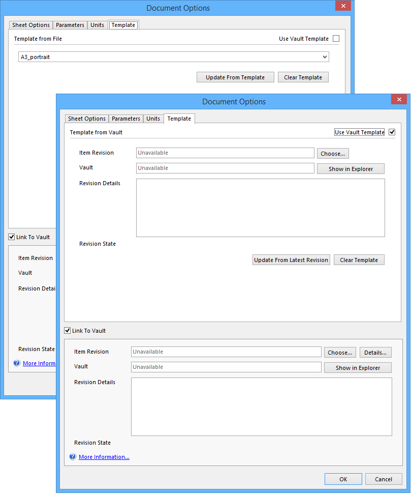
Document Options dialog - Template tab, using Template from File (back) and using Vault Template (front).
Use the dialog's Template tab to utilize, and switch between, default schematic document templates, or remove the active template altogether.
Options/Controls
Template From File

Using a file based template.
In this mode designers can select a file-based template item.
- Template File - this field reflects the template currently in use for the active schematic sheet. It will be blank if no template is currently being used. The field's drop-down lists all default templates shipped as part of the Altium Designer installation. Simply select a template to switch to it.
- Update From Template - click this button to update the active schematic sheet with the latest changes made (where applicable) to the currently assigned template.
- Clear Template - use this button to remove the current template, but retain its sheet size. The Template File field will be cleared.
From Vault Template

With the Use Vault Template option enabled.
Check the Use Vault Template option to choose a Vault based revision of a template item.
- Revision State - displays the current lifecycle state for the selected revision and lists whether that revision is the latest (up to date) or not (out of date).
- Revision Details - displays any given information about the selected revision.
- Vault - lists which vault is linked to. Click Show in Explorer to open the Vault Explorer.
- Item Revision - click the Choose button to access a standard Open dialog which allows you to browse to and open, the required template file, stored outside of the default installation Templates folder.
- Update From Latest Revision- click this button to update the active schematic sheet from the latest revision of the selected template in the Vault.
- Clear Template - use this button to remove the current template, but retain its sheet size. The Template File field will be cleared.
- Link to Vault - check this option to link the document template to a Vault.
- Item Revision - lists which template revision is currently being used. Click the Choose button to select another revision from the Vault. Click the Details button to open a detailed list of revision information in the workspace.
- Vault - select which Vault to link to. Click the Show in Explorer button to open the Vault Explorer.
- Revision Details - displays any given details about the selected revision.
- Revision State - displays the current lifecycle state for the selected revision and lists whether that revision is the latest (up to date) or not (out of date).