Support for Apertures
PCB layers are created from photographic film that has been exposed to light. Apertures are the physical openings through which the light shines on the film. CAM data includes aperture definitions (size and shape), plus instructions about where to flash the light through apertures, and where to draw lines on the film by moving between locations with the light beam still on. Different pad sizes will be created by flashing different apertures on the film; thicker or thinner tracks will be drawn on the film by dragging the light beam across the film through larger or smaller apertures.
As technology evolves, physical apertures may drop out of the PCB manufacturing process altogether. Even now, many modern laser plotters transcend the need for physical lens apertures, simulating the corresponding shapes on the film with raster operations.
So far, these advances have not changed the way we talk about CAM images. Every CAM file requires an aperture list, regardless of whether these images will ever really be transferred to the film through physical apertures. Every new CAM document you create will contain a blank Aperture Table. This table is filled automatically when you import CAM data with embedded apertures, such as RS-274-X Gerber formats, or ODB++ data. If you're importing a format that does not embed apertures, such as Gerber's RS-274-D, you will need to include an aperture list as well.
Aperture Lists
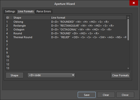
Gerber formats are standardized, but aperture lists are not. Every CAM exporter has its own format for aperture keywords and specifiers, and this can make it difficult to import aperture lists. The CAM Editor eases this burden by providing dozens of aperture list wizards for the prevailing formats – as well as many legacy ones – that you may encounter. If any of these wizards need to be altered to fit the data you typically receive, or if you want to create a new wizard from scratch, you may do so by editing individual line formats.
When importing aperture lists, you can set the detection to automatic, which will search through all of the defined aperture wizards for one that will import your file without errors. The CAM Editor gives you complete access to all of these wizards, should you need to make any changes.
Aperture list wizards all have general settings and line format instructions. General settings include such information as where to start and stop reading aperture lines, what units and scale to use, and whether more than one aperture definition may exist on a single line.
Individual line formats are defined by tags and keywords for each shape. The CAM Editor contains an arsenal of intrinsic shapes, including all of those supported by the ODB++ format. Some shapes will have the same tags: diamonds, bullets, ellipses, rectangles, and oblongs are all defined by width and height. Others are more complicated and require additional parameters. When you are creating new or editing existing aperture wizards, you must match the tag sequence and format with those values that are provided in the aperture lists you want to import.
For example, the CAM Editor's own wizard begins each line format with the D code tag: <D>. Next, the shape is identified by its name, followed by its dimensions. A space in the Line Format between tags translates to the space between one character and the next, so it could correspond to a series of spaces or tab delimiters. The string tag <S> refers to any set of characters isolated by such spaces.
Failures to import an aperture list are reported. Although the list may continue to import, the best practice would be to identify the errors, update the wizard accordingly, then import the aperture list again.
The following table is a complete list of the tags recognized by the CAM Editor. The latter portion of this article provides examples of each shape supported by the editor and dimensions showing how these tags relate to each shape.
|
<D> |
D Code |
|
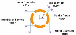
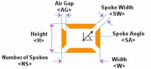
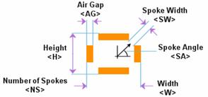
<SA> |
Spokes Angle |
|
<A> |
Aperture |
|
<NS> |
Number of Spokes |
|
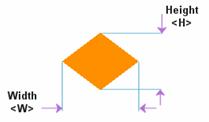
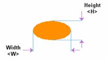
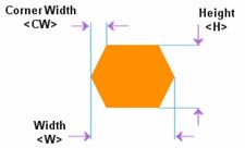
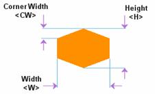
<W> |
Width |
|
<SW> |
Spokes Width |
|
<H> |
Height |
|
<AG> |
Air Gap |
|
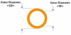
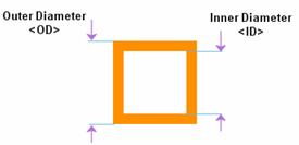
<ID> |
Inner Diameter |
|
<RW> |
Ring Width |
|
<OD> |
Outer Diameter |
|
<RG> |
Ring Gap |
|
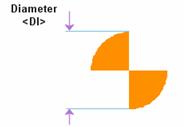
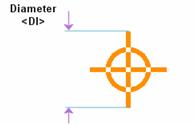
<DI> |
Diameter |
|
<NR> |
Number of Rings |
|
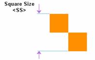
<SS> |
Square Size |
|
<LL> |
Line Length |
|
<B> |
Base |
|
<LW> |
Line Width |
|
<CR> |
Corner Radius |
|
<R> |
Rotation |
|
<CW> |
Corner Width |
|
<HO> |
Hole |
|
<C> |
Corners |
|
<S> |
String |
Aperture Table
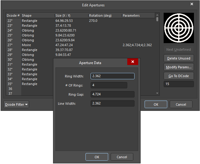
The Aperture Table (displayed in the Edit Apertures dialog) has the task of listing all apertures in a single table, which becomes difficult since no tags are common to all aperture shapes. Instead, the aperture table includes a Size (X:Y) column, which only sometimes corresponds to horizontal and vertical measurements. Those shapes, which only have one dimension, such as square and round shapes, and the Y value you enter in this table will be ignored and overwritten with the X value.
For all other shapes, the X value will be the horizontal or an otherwise dominant dimension, and the Y value will be the vertical or otherwise secondary value. For example, a Donut has two dimensions: inner and outer diameters. The X value will be the outer diameter since it constrains the inner diameter. Any additional tags will correspond to the fields in the Aperture Data dialog, which is available for complex shapes, such as Moire, by clicking within the associated Parameters column. Complex shapes may also access the Rotation (deg) drop-down, where you may select the desired rotation value.
Hovering the mouse over the Size or Parameters fields in the Aperture Table of the Edit Apertures dialog will display tooltip information, in which the values are associated with the corresponding tags for that particular shape, as shown.
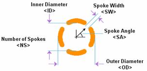
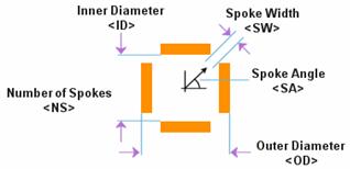
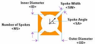
Supported Aperture Shapes
The following is a list of the aperture shapes supported by the CAM Editor. For each shape, the associated tags used to define the properties of the shape are also shown.
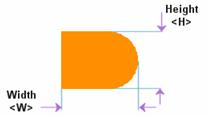
Bullet
Butterfly
Butterfly Square
Diamond
Donut
Donut Square
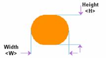
Ellipse
Hexagon Horizontal
Hexagon Vertical
Moire
Oblong
Octagon
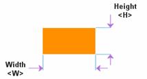
Rectangle
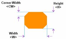
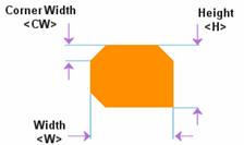
Rectangle Chamfered
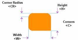
Rectangle Rounded
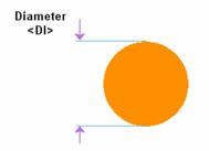
Round
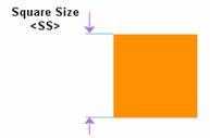
Square
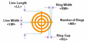
Target
Thermal
Thermal Rectangle
Thermal Rectangle Open
Thermal Round
Thermal Square
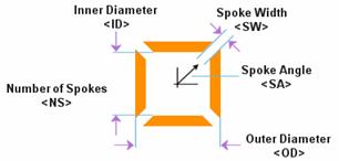
Thermal Square Open
Thermal Square Round
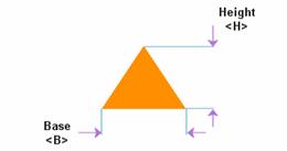
Triangle