Support for Import & Export
Importing Files Using Quick Load
The Quick Load command allows you to import all CAM files located in a single folder. Quick Load imports all traditional CAM documents (e.g., Gerber, ODB++, Aperture List Files (*.lst), and IPC-D-356 netlists) that are stored in a single folder. If your board has any holes, e.g., through holes or blind or buried vias, you must provide, at the very least, the signal layers (e.g., Gerber files for top and bottom) and one or more NC Drill file (Excellon 2 format).
Setting Up Import Options
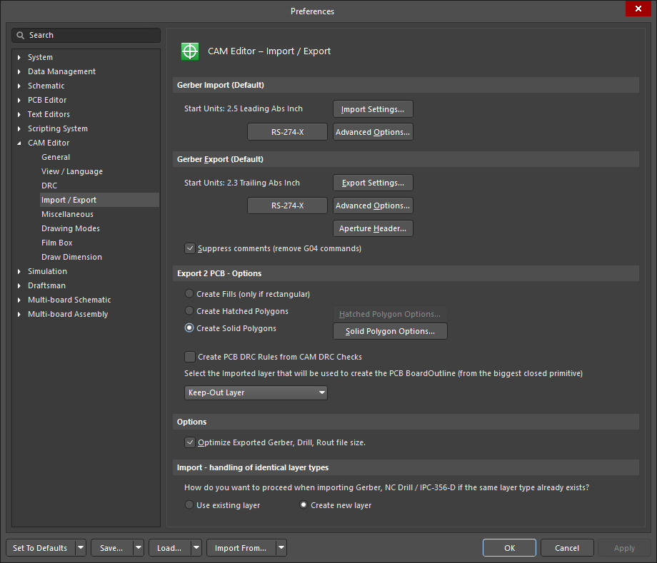
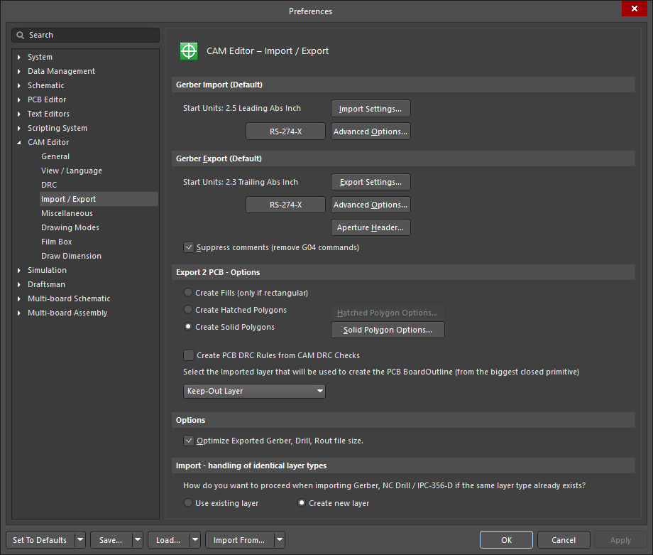
Before importing the Gerber, NC drill, and netlist files into the new CAM document, you may set up import options, such as the Gerber Import settings. To do so, select File » Setup » Import/Export from the main menu to open the CAM Editor - Import/Export page of the Preferences dialog.
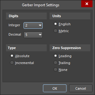
Click on Import Settings from the Gerber Import (Default) area to display the Gerber Import Settings dialog, where you may set up the default import settings for Gerber files.
You may specify if you would like the CAM Editor to create new layers, even if layers with identical layer types already exist, or to use the existing layers. Using the existing layers may be useful when loading data for more than one board in the same files using different steps in order to panelize the loaded PCBs onto the same CAM panel, which is known as multi-step panelization.
To check the file extensions or add a new extension, click on the CAM Editor - Miscellaneous page of the Preferences dialog.
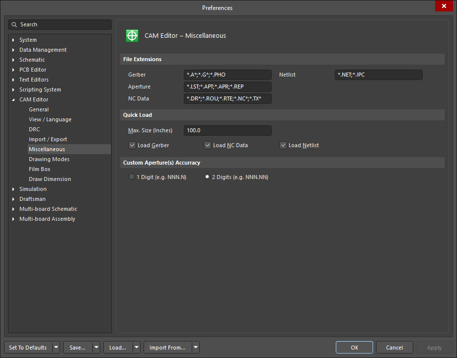
The file extensions listed here determine the type of an imported file, for example, a quick load of Gerber files will look for and load all files with an *.A, *.G . or *.PHO extension. You may add any additional extensions required, separated by a semi-colon (;) from the previous entry.
Importing CAM Files Using Quick Load
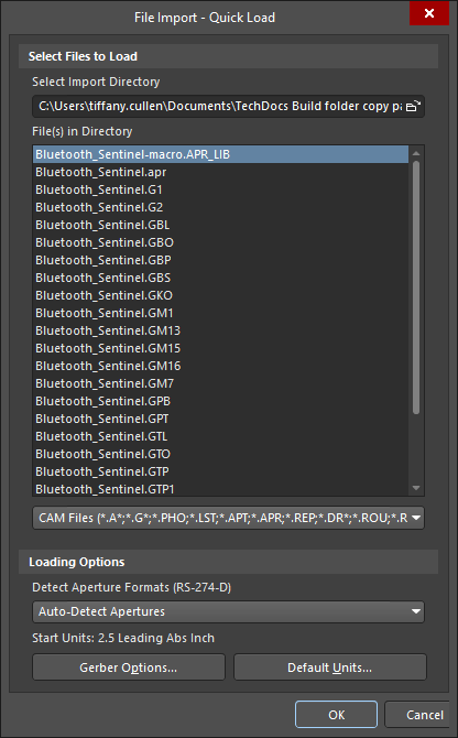
To import the Gerber, NC Drill, and netlist files into the new CAM document (File » New » CAM Document), select File » Import » Quick Load from the main menu to open the File Import - Quick Load dialog. From this dialog, you may specify the aperture format from the Detect Aperture Formats drop-down list and access the Gerber Options or Default Units buttons to display the setup dialogs.
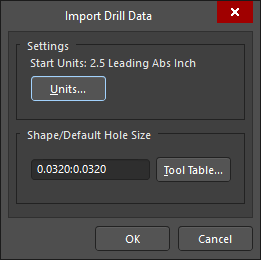
When the Gerber files have finished importing, the Import Drill Data dialog will open.
Once completed, NC files will be imported into the CAM Editor and display in the design window along with a Quick Load Process Report log file. IPC netlist files will be loaded last.
Importing ODB++ Files Using Quick Load
The ODB++ import option imports ODB++ files into the CAM Editor. If the NC drill data has been generated from the PCB Editor, you must separately import the NC drill data after the ODB++ import has been completed. Other CAD/CAM packages should already have the drill hole data present in the ODB++ structure, therefore a separate import of the NC drill data is unnecessary.
To do so, select File » New » CAM Document from the main menu. Next, select File » Import » Quick Load to open the File Import - Quick Load dialog.

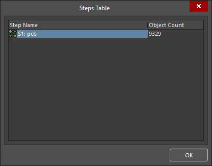
Once the files have been imported, the Steps Table dialog will open. This dialog displays all of the ODB++ steps that have been defined in the loaded ODB++ database for the current document. Steps are identified by Step Name and the Object Count associated with that step.
Once all default values for step assignment and the design are imported, a log file will be produced. The Steps tab in the CAM panel will be refreshed, where you may add or modify steps by right-clicking and selecting the appropriate command from the pop-up menu.
Importing NC Drill Files
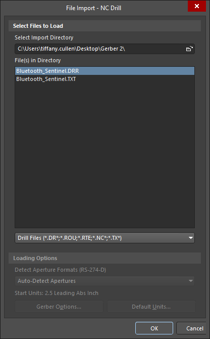
To import NC drill information related to your design, select File » Import » Drill from the main menu to open the File Import NC Drill dialog. The file extension for NC Drill data created in the Altium NEXUS PCB Editor is .txt.
The Import Drill Data dialog will display after the NC Drill files have been imported.
Once the defaults are accepted, the NC drill data will be imported on a separate layer whose layer name is based on the file name, for example, _4_port_serial_interface.txt_. A log file will also be produced.
Importing Other File Types
You can use the File » Import menu options to import the following file types individually or as a selection: Gerber; ODB++; Netlist; Drill; Mill/Rout and DXF/DWG.
If there are no embedded apertures included in the files you want to import, you may load an Aperture file using pre-determined template formats by selecting File » Import » Aperture File, or load a Custom Aperture Library file (.lib) by selecting File » Import » Custom Aperture Library File (.LIB).
Importing Mill Rout Files
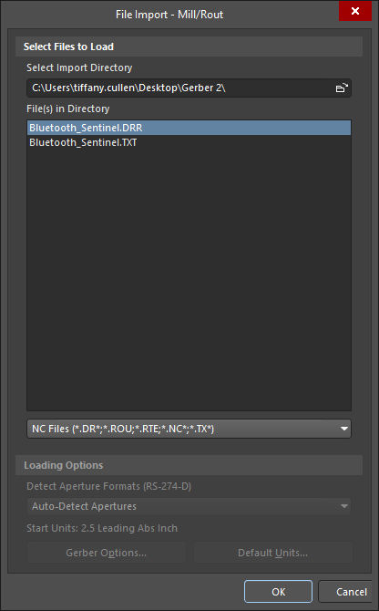
Create a new CAM file by selecting File » New » CAM Document from the main menu, then select File » Import » Mill/Rout to open the File Import - Mill/Rout dialog.
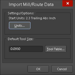
The Import Mill/Rout Data dialog will display after the Mill/Rout files are imported. The data will be imported on a separate layer whose layer name is based on the filename, for example, 'cam.rte'. A log file is also produced. If you want to modify the Mill Rout layer, you must be in the NC Editor mode. Select View » NC Editor to access the Rout menu options.
Exporting Files from the CAM Editor
All CAM Editor outputs are generated through the File » Export menu. You will need to export files when you have made modifications to the original outputs or if you require the Test Point or NC Drill data saved in Gerber format.
The following export options are available when in the CAM Editor:
- Gerber
- Netlist
- IPC-D-350
- Save Drill
- Mill/Rout
- DXF
- Part Centroids
- Aperture List
- Library
- Bitmap (*.bmp).
You must be in NC Editor mode to access the Drill export option.
Exporting Gerbers
Select File » Setup » Import/Export from the main menu to open the CAM Editor Import/Export page of the Preferences dialog. Make sure the default export format is RS-274-X, which is the extended Gerber format that includes the aperture definitions, also known as embedded apertures.
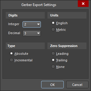
Click the Export Settings button to display the Gerber Export Settings dialog, where you can set up the default export settings for Gerber files.
Select File » Export » Gerber from the main menu to open the Export Gerber(s) dialog.
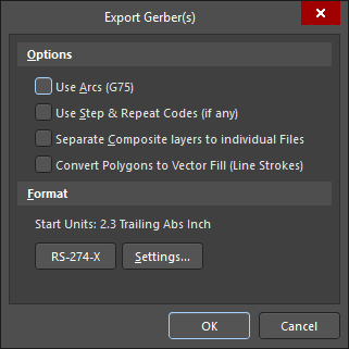
Once the default settings have been finalized, the Write Gerber(s) dialog will open.

Select the Gerber files you wish to export by enabling them in the Writer Gerber(s) dialog. Alternatively, you may select the files for exporting using the right-click menu selections or use the Spacebar key to toggle the selection.
Choose a location for the exported files by clicking the Browse for Folder ( ) button.
Exporting Netlists
You may export netlists in two formats. To do so, use the File » Export » Netlist command to export a netlist in IPC-D-356 format (.net). You may also use the File » Export » IPC-D-350 to export an IPC-D-350 netlist (.ipc). You must have a netlist extracted from the imported data to utilize these commands. If you have not already extracted the netlist, select Tools » Netlist » Extract.
Select File » Export » Netlist to open the Write IPC-D-356 dialog.
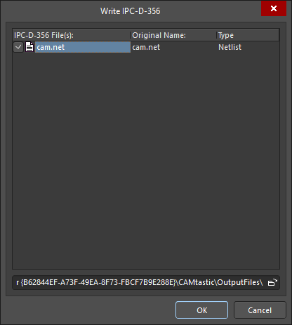
From the Write IPC-D-356 dialog, select the .net file and choose a location and filename for this netlist report.
Export Drill Files
Enter NC Editor mode by selecting View » NC Editor from the main menu, then select File » Export » Drill to open the Export Drill Data dialog.
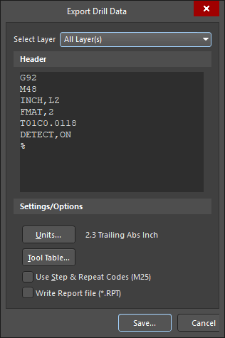
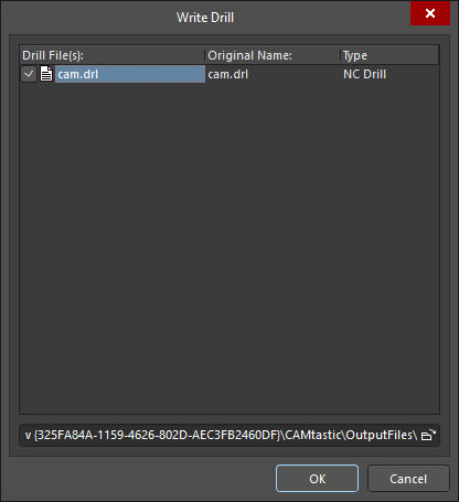
Once the defaults have been accepted, the Write Drill dialog will open. Choose a location and the filename (.drl) for this drill export to export files to the nominated location. Doing so will open the Write Drill dialog.