
Analyzing Your Design using Circuit Simulation
Mixed-Signal Circuit Simulation
Circuit simulation allows the designer to explore their ideas before committing to manufacture. Concepts can be verified and the circuit can be tuned quickly and accurately. Circuit simulation also gives the designer the opportunity to perform measurements that may not be physically possible on the workbench.
The Simulator is a true mixed-signal simulator, meaning that it can analyze circuits that include both analog and digital devices. The Simulator uses an enhanced version of the event-driven XSpice. It is fully SPICE3f5 compatible, as well as providing support for a range of PSpice® and LTSpice® device models.
Getting Started with the Mixed-Signal Simulator
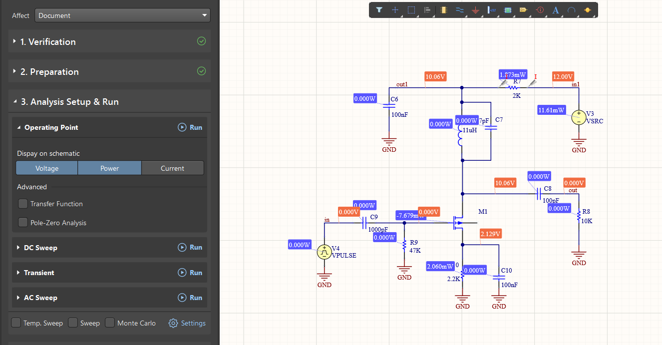 Place and wire the components, configure the simulation sources, and you're ready to start simulating.
Simulations are performed directly from the schematic, and can also be re-run as you analyze the simulation waveforms.
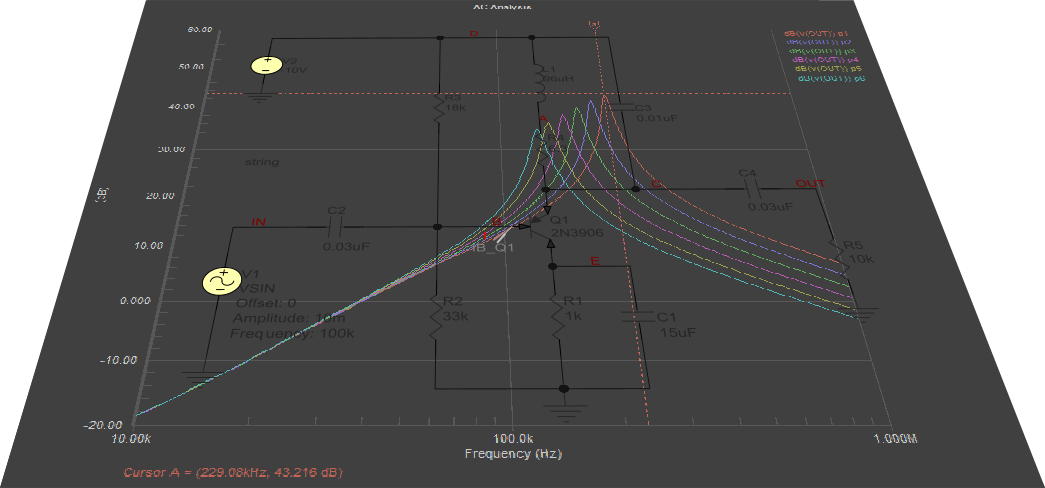
Simulation results are displayed in the built-in waveform viewer, where you can also analyze results data, including Fourier analysis or a broad variety of user-defined measurements.
The simulation netlist is also available, open it to confirm that the generated SPICE is as you expect, and run the simulation directly from the netlist.
► Check out the SPICE Simulation Guide
Working with the Simulation Dashboard
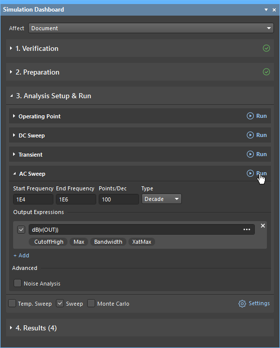 The mixed-signal circuit simulator is configured and driven from the Simulation Dashboard.
The Dashboard provides:
- Verification information - confirm that electrical rules checks are passed and all components have models. Missing models or simulation source issues are flagged, with links to help resolve them.
- Preparation information - Simulation Sources and Probes are listed (click to jump to a source/probe), and additional Sources or Probes can be added.
- Analysis Setup & Run - Quickly configure the required analysis type and the Output Expressions to be plotted, then run the simulation.
- Results - Examine the previous analysis runs, double-click to re-open the waveform, or use the ellipsis menu to access other options.
As well as running a simulation from the Dashboard, you can also configure your circuit, generate a netlist and run a simulation from the Simulate menu.
► Learn more about the Simulation Dashboard and Commands