
Accordion
This document is no longer available beyond version 4.0. Information can now be found here: Length Tuning for version 5
Parent page: PCB Design Objects
 Accordion objects are added to increase the length of a route, the Net Length Gauge indicates the progress towards achieving the required target length.
Summary
The accordion object is a system-created group object. The accordion object is created by the software during interactive length tuning to increase the overall length of a route. The software builds the accordion-shaped section of routing from tracks and/or arcs in accordance with the properties defined in the Accordion mode of the Properties panel. Because the accordion object is a group object, a placed accordion can be interactively reshaped if required.
Availability
The accordion object is placed automatically in the PCB editor when the Interactive Length Tuning command is being used and the route length is shorter than the length specified for that net.
The route length requirement is specified by:
- An applicable Length design rule.
- An applicable Matched Length design rule.
- A user-defined length, specified in the Accordion mode of the Properties panel or Accordion dialog.
Placement
 Accordions are placed when the Interactive Length Tuning command is run, and the route length needs to be increased.
After launching the PCB editor's Route » Interactive Length Tuning command, the cursor will change to a cross-hair and you will enter length tuning (Accordion placement) mode. Placement is made by performing the following sequence of actions:
- Click on the routed net that needs its length to be increased.
- Move the cursor along the route in the direction that the accordion is to be added as shown in the animation above. An accordion will appear and continue to grow as the cursor moves. The accordion properties (length, style, amplitude, and gap) will be in accordance with the current settings defined in the Accordion mode of the Properties panel (more on this below). The amplitude of the accordion is automatically decreased to avoid existing routing and component objects as shown in the image at the top of this page.
- During placement, the cursor can move away from the existing route by up to the current Max Amplitude distance specified in the Properties panel. If the cursor moves further than this, the accordion currently being placed will disappear. Move the cursor back towards the existing route to restore the accordion being placed.
- The accordion will stop growing when the required overall route length is achieved if the Clip to Target Length option is enabled in the Properties panel. Click to complete placement of the accordion.
- Continue tuning other route lengths (placing further accordions) or right-click or press Esc to exit length tuning mode.
Additional actions that can be performed during placement include:
- Press the Tab key to pause placement and access the Accordion mode of the Properties panel from where its properties can be changed on the fly. Click the design space pause button overlay (
 ) to resume placement.
 - The properties of the accordion can also be interactively adjusted during placement using shortcuts. Refer to the Placement Shortcuts section to learn more about the shortcuts.
- The current route length is displayed in the Net Length Gauge. Press the Shift+G shortcut to toggle the gauge on or off.
Placement Shortcuts
The shortcuts available during length tuning include:
| Shortcut | Function |
|---|---|
| Spacebar | Cycle through the three Styles of tuning pattern |
| , (comma) | Decrease amplitude by the amount specified for the Amplitude Increment |
| . (full stop) | Increase amplitude by the amount specified for the Amplitude Increment |
| 3 | Decrease space by the amount specified for the Gap Increment |
| 4 | Increase space by the amount specified for the Gap Increment |
| 1 | Decrease corner miter by the % specified for the Miter Increment |
| 2 | Increase corner miter by the % specified for the Miter Increment |
| Tab | Open the Properties panel in Accordion mode |
| Shift+G | Toggle Length Tuning Gauge on/off |
Graphical Editing
This method of editing allows you to select a placed Accordion object directly in the design space and graphically change its size and shape.
When an Accordion object is selected, its polygonal outline is displayed as shown in the animation below. The outer shape of the polygonal outline is defined by a series of edges: where each edge is represented by an end vertex at each end, shown as a solid white square (A in the image below); and a center vertex in the middle, shown as a hollow white square (B in the image below). Each end vertex represents the location where two edges meet.
 Click and drag on an edge or a vertex to reshape the accordion's polygonal outline, press Shift+Space to change the editing mode.
Standard polygonal shape editing techniques are available for editing the shape.
When editing a polygonal object, there are three editing modes available, Slide/Miter, Incurvate (arc) and Move. The current mode can be changed while dragging a vertex or an edge by pressing Shift+Spacebar to cycle through the three modes.
- Slide/Miter - click and hold on an edge or a center vertex to slide that edge; click and hold on an end vertex to miter the corner.
- Incurvate - click and hold on an edge or a center vertex to incurvate that edge; click and hold on an end vertex to incurvate (arc miter) the corner.
- Move - click and hold on an edge or a center vertex to break that edge into two edges; click and hold on an end vertex to freely move that corner.
Non-Graphical Editing
The following methods of non-graphical editing are available.
Editing via the Accordion Dialog or Properties Panel
Properties page: Accordion Properties
This method of editing uses the associated Accordion dialog and Properties panel mode to modify the properties of an Accordion object.
 and the Accordion mode of the Properties panel (the second image)")
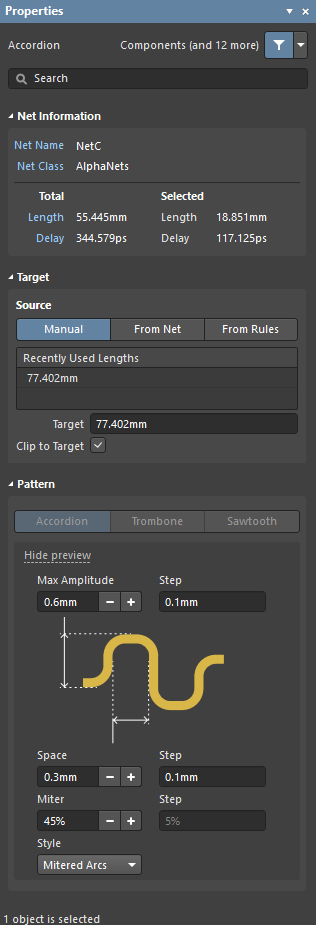 The Accordion dialog (the first image) and the Accordion mode of the Properties panel (the second image)
During interactive length tuning, the Properties panel can be accessed by pressing the Tab key.
After placement, the Accordion dialog can be accessed by:
- Double-clicking on the placed Accordion object.
- Placing the cursor over the Accordion object, right-clicking then choosing Properties from the context menu.
After placement, the Accordion mode of the Properties panel can be accessed in one of the following ways:
- If the Properties panel is already active, select the Accordion object.
- After selecting the Accordion object, select the Properties panel from the Panels button at the bottom right of the design space or select View » Panels » Properties from the main menus.
The properties displayed in the panel and dialog reflect the settings that were used to create the selected accordion.
Editing Multiple Objects
The Properties panel supports editing multiple objects, where the property settings that are identical in all currently selected objects may be modified. When multiples of the same object type are selected manually, via the Find Similar Objects dialog or through a Filter or List panel, a Properties panel field entry can be edited for all selected objects. If values of a property are different for objects in the selection, the appropriate field will be shown as an asterisk (*) – a new property value will be applied to all selected objects.
Editing via a List Panel
Panel page: PCB List, PCB Filter
A List panel allows you to display design objects from one or more documents in tabular format, enabling quick inspection and modification of object attributes. Used in conjunction with appropriate filtering – by using the applicable Filter panel, or the Find Similar Objects dialog – it enables the display of just those objects falling under the scope of the active filter – allowing you to target and edit multiple design objects with greater accuracy and efficiency.