
Split Line
This document is no longer available beyond version 4. Information can now be found here: Defining Board Regions (Standard Rigid-Flex Mode) for version 5
Parent page: PCB Objects
, which run from one edge of the board shape to another edge.") A board is split into distinct regions by placing Split Lines (blue in color), which run from one edge of the board shape to another edge.
A board is split into distinct regions by placing Split Lines (blue in color), which run from one edge of the board shape to another edge.
Summary
A Spit Line is a PCB drawing object used to define Board Regions. Split lines placed across an area of PCB as defined by the board shape outline split that area into two Board Regions. Each Board Region can have a unique Layer Stack assigned to it.
Availability
Split Lines can only be implemented in the PCB Editor with the View mode set to Board Planning Mode (View » Board Planning Mode – press the 1 shortcut).
Choose Design » Define Split Line to place a Split Line. A single board region (for example, that of a newly-created board) is split into two regions by placing a Split Line.
Placement
To place a Split Line:
- Select View » Board Planning Mode (or press the 1 shortcut) to enter Board Planning Mode.
- Select Design » Define Split Line to enter Split Line placement mode.
- Click within the board shape to begin the Split Line definition process. One end of the line will attach to the closest point on the board shape outline to where you clicked, the other end of the line will attach to the cursor.
- Position the cursor in the required location then click once to place the second end.
- You remain in Split Line placement mode, ready to place another Split Line if required. If not, right-click or press Esc to exit Split Line placement mode.
Board Regions are the areas between the Split Lines, and are assigned a default region name.
Graphical Editing
Within a board layout, Board Regions are defined by the positioning of Split Lines. The Split Line can be graphically edited by manipulating the nodes at the end of each line using a select and drag method.
Moving a Split Line
To move a Split Line:
- Select View » Board Planning Mode (or press the 1 shortcut) to enter Board Planning Mode.
- To relocate the end of a line, click, hold and drag it to the required location around the perimeter of the board shape. The cursor will be constrained to the current snap grid.
- The Board Region will be redefined by the new position of the edited Split Line.
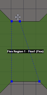 Select and drag a Split Line end node to redefine
a Board Region area.
Removing a Split Line
To delete a Split Line:
- Select View » Board Planning Mode (or press the 1 shortcut) to enter Board Planning Mode.
- Click and hold the split line by one of its end points then press Delete. Alternatively, click, hold and move an endpoint to a point around the board shape that results in the split turning red (signifying an invalid split), then release.