
Bus Properties
Created: April 08, 2021 | Updated: September 01, 2021
| Applies to version: 4
This document is no longer available beyond version 4. Information can now be found here: Bus Properties for version 5
Parent page: Bus
Schematic Editor object properties are definable options that specify the visual style, content and behavior of the placed object. The property settings for each type of object are defined in two different ways:
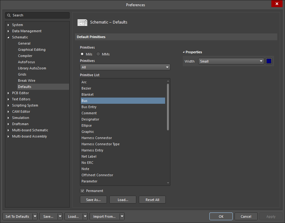
- Pre-placement settings – most Bus object properties, or those that can logically be pre-defined, are available as editable default settings on the Schematic - Defaults page of the Preferences dialog (accessed from the
 button at the top-right of the design space). Select the object in the Primitive List to reveal its options on the right.

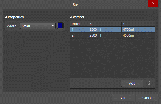
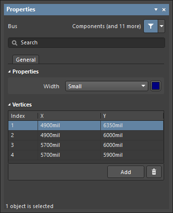
- Post-placement settings – all Bus object properties are available for editing in the Bus dialog and the Properties panel when a placed Bus is selected in the design space.
Properties
- Width - use the drop-down to select the desired width.
Vertices (Properties panel only)
This region is used to modify the individual vertices of the currently selected region object. You can modify the locations of existing vertices, add new vertices or remove them as required. Bus connections between vertex points can be defined and support is also provided for exporting vertex information to and importing from a CSV-formatted file.
- Vertices Grid - lists all of the vertex points currently defined for the object in terms of:
- Index - the assigned index of the vertex (non-editable).
- X - the X (horizontal) coordinate for the vertex. Click to edit.
- Y - the Y (vertical) coordinate for the vertex. Click to edit.
- Add - click to add a new vertex point. The new vertex will be added below the currently focused vertex entry and will initially have the same X,Y coordinates as the focused entry. Click
 to remove the currently selected vertex.