
Part Properties
This document is no longer available beyond version 4. Information can now be found here: Part Properties for version 5
Parent page: Part
Schematic Editor object properties are definable options that specify the visual style, content, and behavior of the placed object. The property settings for each type of object are defined in two different ways:
-
Pre-placement settings – most Part object properties, or those that can logically be pre-defined, are available as editable default settings on the Schematic - Defaults page of the Preferences dialog (access from the
 button at the top-right of the design space). Select the object in the Primitive List to reveal its options on the right.
-
Post-placement settings – all Part object properties are available for editing in the Properties panel when a placed Part is selected in the design space.
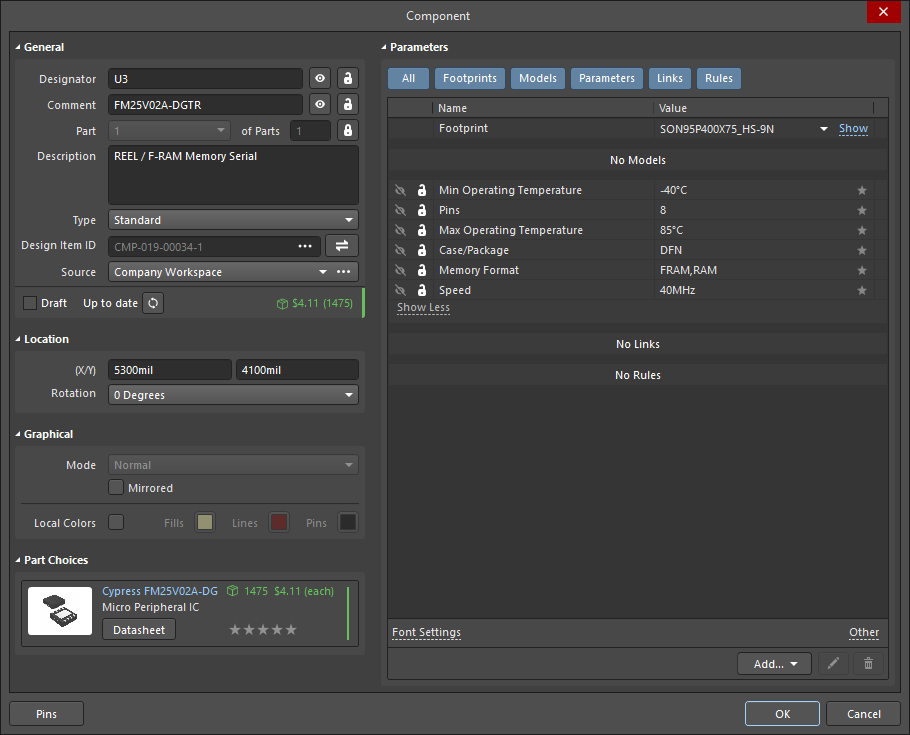
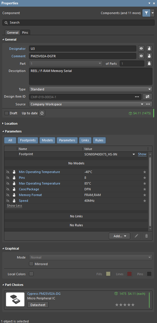
Part Properties
General
- Designator - enter the designator. Toggle the eye icon to show/hide the designator. Use the lock icon to lock/unlock the designator.
- Comment - enter the name. Toggle the eye icon to show/hide the name. Use the lock icon to lock/unlock the name.
- Part <x> of Parts - displays the number of the selected part and the total number of parts. Use the drop-down to select the number of the associated part then enter the total number of parts. Click
 to lock/unlock the fields.
 - Description - the component/part description.
- Type - Select one of the following component types for the component footprint here. The available types are:
Standard- components that possess standard electrical properties, are always synchronized between the schematic and PCB (the footprint, pins/pads, and net assignments must all match), and are included in the BOM. An example is a standard electrical component, such as a resistor.Mechanical- components that do not have electrical properties, are not synchronized (you must manually place them in both editors), and are included in the BOM. An example is a heatsink.Graphical- components that do not have electrical properties are not synchronized (you must manually place them in both editors), and are not included in the BOM. An example is a company logo.Net Tie (In BOM)- components that are used to short two or more different nets together, are always synchronized between the schematic and PCB (the footprint, pins/pads, and net assignments must all match), and are included in the BOM. They differ from a Standard component in that connectivity created by copper within the footprint is not checked; it is this copper that allows the nets to be shorted. Note: enable the Verify Shorting Copper option in the Design Rule Checker dialog to verify that there is no unconnected copper within the component.Net Tie (No BOM)- components that are used to short two or more different nets together, are always synchronized between the schematic and PCB (the footprint, pins/pads, and net assignments must all match), and are not included in the BOM. They differ from a Standard component in that connectivity created by copper within the footprint is not checked; it is this copper that allows the nets to be shorted. Note: enable the Verify Shorting Copper option in the Design Rule Checker dialog to verify that there is no unconnected copper in the component.Standard (No BOM)- components that possess standard electrical properties, are always synchronized between the schematic and PCB (the footprint, pins/pads, and net assignments must all match), and are not included in the BOM. An example is a testpoint component that you want to exclude from the BOM.Jumper- components that are used to include wire links in a PCB design, for example, on a single-sided PCB that cannot be fully routed on one layer. For this component type, the component footprint and pins are synchronized between the schematic and PCB but the net assignments are not, and the component is included in the BOM. As well as selecting this option at the component level, both of the pads in the component must have their JumperID set to the same non-zero value. Jumper type components do not need to be wired on the schematic; they only need to be included on the schematic if they are required in the BOM. If they are not required in the BOM, they can be placed directly in the PCB where the Component Type is set, the JumperIDs are set, and the Nets manually assigned for the pads.
- Design Item ID - this field lists the name of the component selected. Click
 to open the Replace Component (Managed) dialog or Replace Component (File-based) dialog, depending on whether the component is managed or non-managed. This dialog grants access to full details of the selected component (Parameters, Models, Part Choices, Supplier data, etc.), component comparison, and the ability to replace the current component with another, among other possibilities. If another component is selected as a replacement, this field will then display the full Design Item ID for the newly selected component. Click the Validate button (
 ) to display information regarding where the component resides. If it is non-managed, the file path in which it is saved on your computer will appear. If it is managed, the information will indicate that the component was simply found.
 - Source - displays the name of the source library of the component. Click to search for and select the desired library.
-
Revision state - this field displays the current lifecycle state of the selected component revision, with the color icon and name of the revision state.
- Revision status - if the selected component revision is in an applicable state (allowed for use in designs) the entry will either reflect that the revision is the latest (
Up to date) or not (Out of date). If the revision is in an inapplicable state (not allowed for use in designs) the entry will displayNot applicable. Click the button to update the component to the latest revision.
 icon.
icon.-
Component issues - if a selected component sourced from the connected Altium 365 Workspace has any health issues, an indication of this will be presented by the
 (for errors) or
  (for fatal errors) icon. The number at the right of the icon indicates the number of found issues. Click the down arrow at the right of the number to see the short descriptions of the issues.
An example of library health issues found.
- Supply Chain Data - this field displays the supply chain information from related Part Choice:
- Median unit price. This entry will be displayed in red text if there are no prices, or the price = 0.
- Stock. This entry displays the total sum of the stock available from the suppliers enabled as part of the Altium Parts Provider source for your Workspace.
- Manufacturer Lifecycle Bar. Hover over the bar for an informative tool-tip. This can appear in one of four states:
- White/Gray = Default, unknown or no information
- Green = New or Volume Production states
- Orange = Not Recommended for New Design
- Red = Obsolete or EOL
Location
- (X/Y)
- X (first field) - the current X (horizontal) coordinate of the reference point of the object, relative to the current design space origin. Edit to change the X position of the object. The value can be entered in either metric or imperial; include the units when entering a value whose units are not the current default.
- Y (second field) - The current Y (vertical) coordinate of the reference point of the object, relative to the current origin. Edit to change the Y position of the object. The value can be entered in either metric or imperial; include the units when entering a value whose units are not the current default.
- Rotation - use the drop-down to select the rotation. Choices are
0 Degrees,90 Degrees,180 Degrees, and270 Degrees.
Parameters
- Grid - lists the Name and Value of the parameters associated with the currently selected component. Use to lock/unlock a listed parameter. Parameter values can be manually entered, or selected from a drop-down menu list that offers values sourced from all the available components of that type. You may toggle the eye icon to show/hide the parameter.
-
Favorites - parameters marked as Favorites will be shown in the Parameters list, while those not marked will be hidden. Hover to the right of a parameter filter’s name and click the
 icon to set the filter as a Favorite. To remove a parameter as a Favorite, click the icon again.
 - Font - click on the displayed font to change the font style.
- Other - click to open a drop-down to change additional options:
- Show Parameter Name - enable to show the parameter name.
- Allow Synchronization with Database - enable to synchronize with the database. This option is used to control if the comment can be updated. By default, these options are enabled to always allow synchronization with the source library/database. You may disable this option to prevent that comment from being included in an update process.
- (X/Y) - enter the X and Y coordinates.
- Rotation - use the drop-down to select the rotation. Choices are:
0°,90°,180°, and270°. - Autoposition - check to enable auto-positioning, meaning that the parameter is positioned automatically every time the associated component is rotated. Disable this option to keep the parameter position to the associated component when it is rotated.
- Add - click to add a parameter, such as a footprint, model, or rule, among others. Click
 to delete a selected entry from the grid. Click
  to edit the parameter via the parameter's respective dialog.
Graphical
- Mode - use the drop-down to select the desired mode. If no modes other than Normal are available, this drop-down will be grayed out.
- Mirrored - enable to mirror the part.
- Local Colors - Enable the local color option and the schematic component's fill, line, and pin colors are overridden with the colors from the Fill, Lines, and Pins color boxes respectively. Disable this option to use the predefined colors from the library.
Part Choices
- Part Name - click to be lead to additional information about the part, provided directly from the supplier.
- Datasheet - click this button to be lead to the product's latest information, directly from the supplier's website.
- SPN(s) - an SPN (Supplier Part Number) contains the following information:
- Colored tile banner showing the supplier name and price. The color reflects the risk associated with choosing that supplier. The risk can change at any time based on the availability and price data received from the Altium Parts Provider.
- Green = Best
- Orange = Acceptable
- Red = Risky
- Supplier part number (linked to the part on the Supplier's website)
- Last updated icon with details displayed in the tooltip, color indicates:
- White/Gray = Default, updated less than one week ago
- Orange = 1 week < last update < month ago
- Red = last update > 1 month ago
- Country code for the Supplier location (ISO alpha 2); colored red if unknown.
- Part source, details displayed in the tooltip.
- Stock quantity; red if no stock available.
- Unit price, red if no price available. Unit price includes currency icon, currency is determined by the location of the supplier.
- Available price breaks, with Minimum Order Quantities.
- Colored tile banner showing the supplier name and price. The color reflects the risk associated with choosing that supplier. The risk can change at any time based on the availability and price data received from the Altium Parts Provider.
Pins
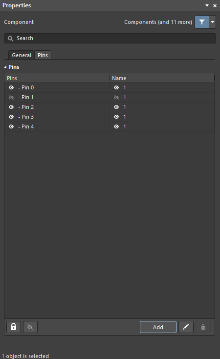
This region lists the Pins and Names for all the pins of the selected component. Use the eye icon to show/hide the pin. Use the lock icon to lock/unlock the pins.
- Add - click to add a pin. Click to delete a selected entry from the table. Click to open the Component Pin Editor dialog in which you can view all pins for either the component in the active schematic library document or a placed component (or part thereof) in the schematic editor.