
Port Properties
Created: January 25, 2021 | Updated: August 23, 2021
| Applies to version: 4
This document is no longer available beyond version 4. Information can now be found here: Port Properties for version 5
Parent page: Port
Schematic Editor object properties are definable options that specify the visual style, content and behavior of the placed object. The property settings for each type of object are defined in two different ways:
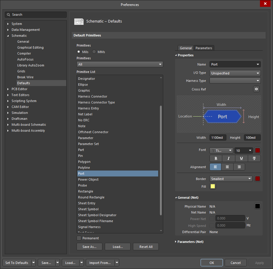
- Pre-placement settings – most Port object properties, or those that can logically be pre-defined, are available as editable default settings on the Schematic - Defaults page of the Preferences dialog (accessed from the
 button at the top-right of the design space). Select the object in the Primitive List to reveal its options on the right.
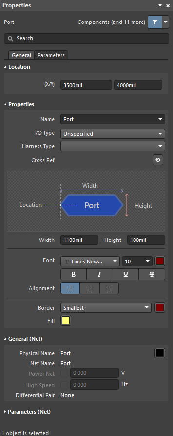
- Post-placement settings – all Port object properties are available for editing in the Port dialog and the Properties panel when a placed Port is selected in the design space.

General Tab
Location (Properties panel only)
- (X/Y)
- X (first field) - the current X (horizontal) coordinate of the reference point of the object, relative to the current design space origin. Edit to change the X position of the object. The value can be entered in either metric or imperial; include the units when entering a value whose units are not the current default.
- Y (second field) - The current Y (vertical) coordinate of the reference point of the object, relative to the current origin. Edit to change the Y position of the object. The value can be entered in either metric or imperial; include the units when entering a value whose units are not the current default.
Properties
- Name - the name of the port.
- I/O Type - defines the electrical properties of the port. Select an option from the drop-down list.
- Harness Type - use the drop-down to select the type of harness.
- Cross Ref - this field displays cross-reference values that are applied to the port.
- Width - can be edited.
- Height - can be edited.
- Font - use the controls to select the desired font, font size, color, and attributes to bold, italicize, etc., if desired.
- Alignment - click the desired alignment setting.
- Border - use the drop-down to select the default from the available choices. Click on the colored box to access a drop-down from which you can select the default color.
- Fill - click on the color box to access a drop-down from which you can select the default color.
General (Net)
Displays the properties of the nets assigned to the port. Update as needed.
Parameters (Net)
- Selection buttons - click the desired objects to display in the grid.
- Add - use the drop-down to add the desired object(s) then define the values.
Parameters Tab

Parameters
Use this region to manage parameters attached to the currently selected port object.
- Grid - lists the Name and Value of the parameters currently defined for the port. You can edit the fields directly if desired. Use
 and
and  to show/hide the parameter. Use the lock icon to lock/unlock the selected parameter.
 - Font Settings - click to open a menu to define the font.
- Other - click to open a drop-down to change additional options:
- Show Parameter Name - enable to show the name of the parameter.
- Allow Synchronization with Database - enable to synchronize with the database.
- X/Y - enter the X and Y coordinates.
- Rotation - use the drop-down to select the rotation.
- Autoposition - check to enable auto-positioning.
- Add - click to add a parameter. Use
 to delete a selected entry from the table.