
Rectangle Properties
Created: April 09, 2021 | Updated: April 09, 2021
| Applies to version: 4
This document is no longer available beyond version 4. Information can now be found here: Rectangle Properties for version 5
Parent page: Rectangle
Schematic Editor object properties are definable options that specify the visual style, content and behavior of the placed object. The property settings for each type of object are defined in two different ways:
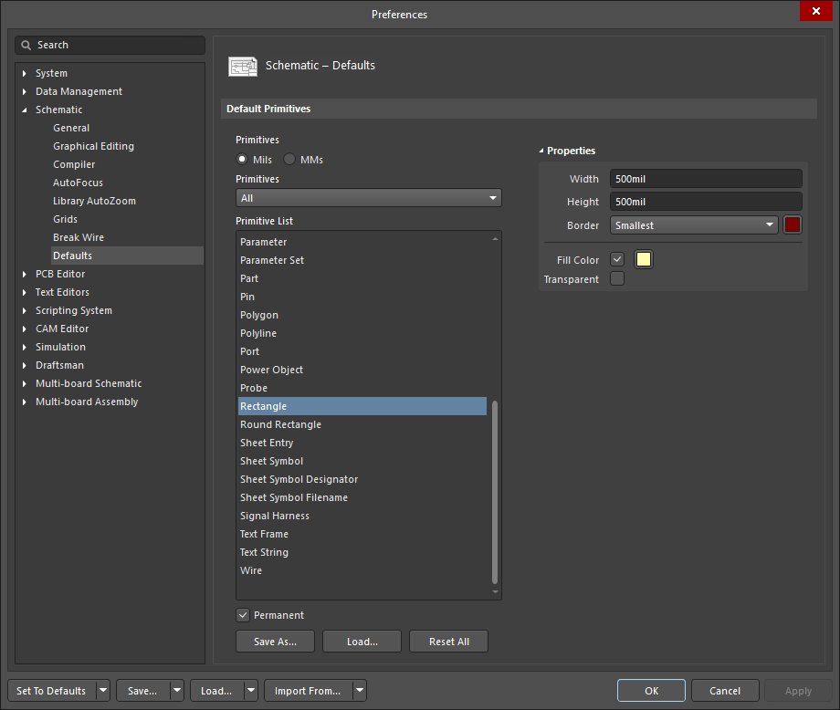
- Pre-placement settings – most Rectangle object properties, or those that can logically be pre-defined, are available as editable default settings on the Schematic - Defaults page of the Preferences dialog (accessed from the
 button at the top-right of the design space). Select the object in the Primitive List to reveal its options on the right.
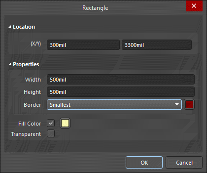
- Post-placement settings – all Rectangle object properties are available for editing in the Rectangle dialog and the Properties panel when a placed Rectangle is selected in the design space.
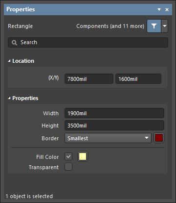
Location (Properties panel only)
- (X/Y)
- X (first field) - the current X (horizontal) coordinate of the reference point of the object, relative to the current design space origin. Edit to change the X position of the object. The value can be entered in either metric or imperial; include the units when entering a value whose units are not the current default.
- Y (second field) - The current Y (vertical) coordinate of the reference point of the object, relative to the current origin. Edit to change the Y position of the object. The value can be entered in either metric or imperial; include the units when entering a value whose units are not the current default.
Properties
- Width - enter the width of the object, which may be edited.
- Height - enter the height of the object, which may be edited.
- Border - use the drop-down to select the default from the available choices. Click on the color box to access a drop-down from which you can select the default border color.
- Fill Color - check to enable fills. Click on the color box to access a drop-down from which you can select the default fill color.
- Transparent - check to make the primitive transparent.