
Sheet Entry Properties
Created: April 09, 2021 | Updated: August 23, 2021
| Applies to version: 4
This document is no longer available beyond version 4. Information can now be found here: Sheet Entry Properties for version 5
Parent page: Sheet Entry
Schematic Editor object properties are definable options that specify the visual style, content and behavior of the placed object. The property settings for each type of object are defined in two different ways:
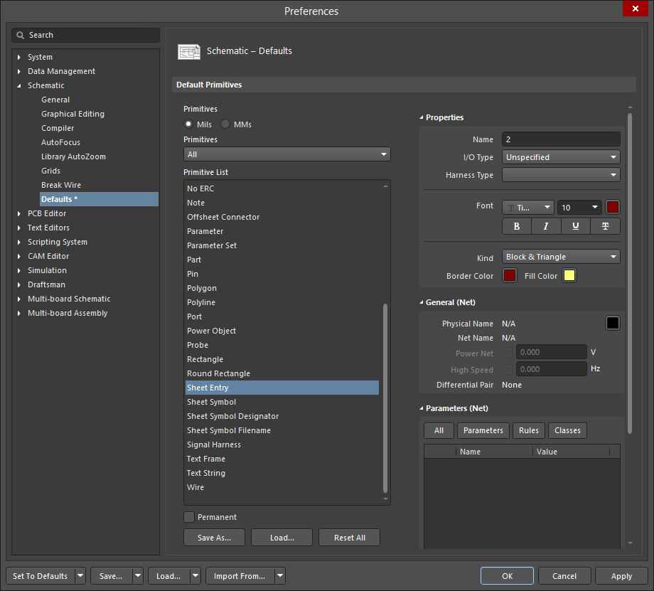
- Pre-placement settings – most Sheet Entry object properties, or those that can logically be pre-defined, are available as editable default settings on the Schematic - Defaults page of the Preferences dialog (access from the button at the top-right of the design space). Select the object in the Primitive List to reveal its options on the right.
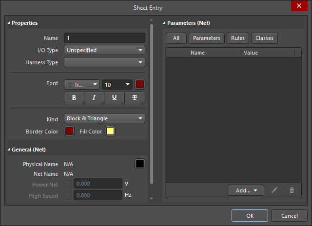
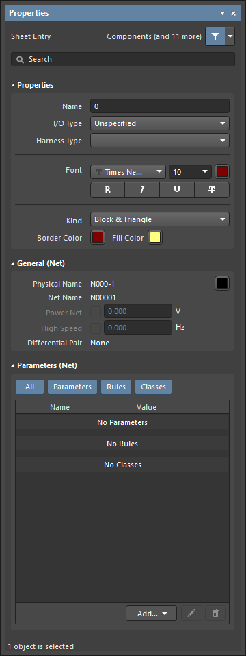
- Post-placement settings – all Sheet Entry object properties are available for editing in the Sheet Entry dialog and the Properties panel when a placed Sheet Entry is selected in the design space.
Properties
- Name - the name of the sheet entry.
- I/O Type - use the drop-down to select the I/O type for the sheet entry.
- Harness Type - use the drop-down to select the type of harness.
- Font - use the controls to select the font, font size, font color, and add any desired special characteristics to the font, such as bold, italics, and underlining.
- Kind - use the drop-down to select the kind of text.
- Border Color - click the color box to access controls to select the border color.
- Fill Color - click the color box to access controls to select the border color.
General (Net)
Displays the properties of the nets assigned to the object. Update as needed.
Parameters (Net)
- Selection buttons - click the desired objects to display in the grid.
- Add - use the drop-down to add the desired object(s) then define the values.