
Sheet Symbol Properties
This document is no longer available beyond version 4. Information can now be found here: Sheet Symbol Properties for version 5
Parent page: Sheet Symbol
Schematic editor object properties are definable options that specify the visual style, content and behavior of the placed object. The property settings for each type of object are defined in two different ways:
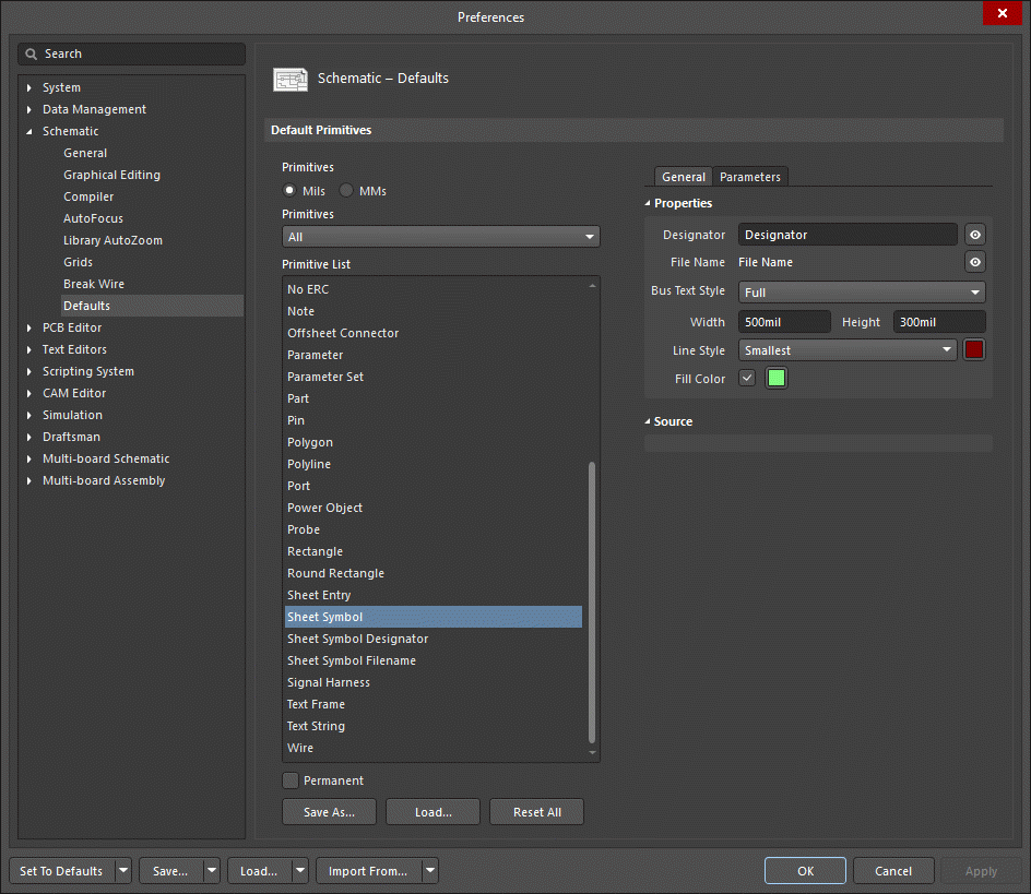
- Pre-placement settings – most Sheet Symbol object properties, or those that can logically be pre-defined, are available as editable default settings on the Schematic - Defaults page of the Preferences dialog (access from the
 button at the top-right of the design space). Select the object in the Primitive List to reveal its options on the right.
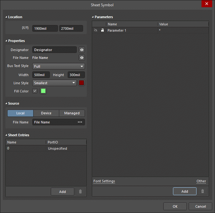
- Post-placement settings – all Sheet Symbol object properties are available for editing in the Sheet Symbol dialog and the Properties panel when a placed Sheet Symbol is selected in the design space.
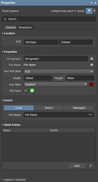
General Tab
Location (Dialog and Properties panel only)
- (X/Y)
- X (first field) - the current X (horizontal) coordinate of the reference point of the object, relative to the current design space origin. Edit to change the X position of the object. The value can be entered in either metric or imperial; include the units when entering a value whose units are not the current default.
- Y (second field) - The current Y (vertical) coordinate of the reference point of the object, relative to the current origin. Edit to change the Y position of the object. The value can be entered in either metric or imperial; include the units when entering a value whose units are not the current default.
Properties
-
Designator - the current name for the sheet symbol. This field is used to provide the sheet symbol with a meaningful name that will distinguish it from other sheet symbols placed on the same schematic sheet. Typically the name will reflect the overall function of the schematic sub-sheet that the symbol represents. Toggle
 or
or  to show/hide the designator.
 - File Name - the current schematic document referenced by the sheet symbol. Toggle or to show/hide the file name.
- Bus Text Style - use the drop-down to select the style of the bus text. Choices are Full or Prefix.
- Width - can be edited.
- Height - can be edited.
- Line Style - use the drop-down to select the default from the available choices. Click on the color box to access a drop-down from which you can select the default line color.
- Fill Color - check to enable fills. Click on the color box to access a drop-down from which you can select the default fill color.
Source (Dialog and Properties panel only)
- Local / Device / Managed - the source of the file.
- File Name - displays the current schematic document referenced by the sheet symbol. It is this field that provides the link between the sheet symbol and the schematic sub-sheet that the symbol represents. Click
 to open the Choose Document to Reference dialog to choose the required target sub-sheet. The dialog presents a listing of all source schematic sheets in the project (with the exception of the sheet upon which the symbol is currently placed).
- File Name - displays the current schematic document referenced by the sheet symbol. It is this field that provides the link between the sheet symbol and the schematic sub-sheet that the symbol represents. Click
Sheet Entries (Properties panel only)
- Grid - lists the Name and PortIO Type of all of the sheet entries currently defined for the sheet symbol. When there are sheet entries in the grid, the following additional options are available when an entry is selected:
- Font - click to configure the font style of the sheet entry.
- Other - click to open a drop-down to change additional options:
- Kind - use the drop-down to select the kind of sheet entry.
- Border Color - click to access controls to choose the border color.
- Fill Color - click to access controls to choose the fill color.
- Add - click to add a sheet entry. Use
 to delete a selected entry from the table.
Parameters Tab
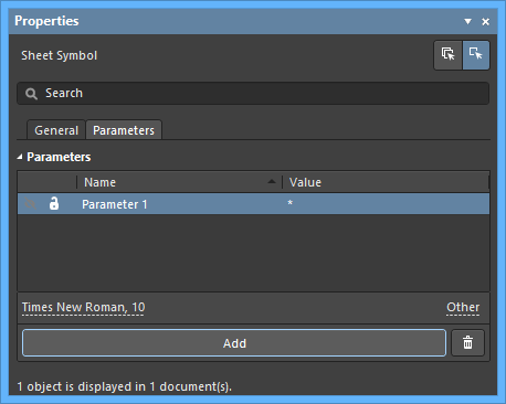
Parameters
- Grid - lists the Name and Value of all of the parameters currently defined for the sheet symbol. When there are parameters in the grid, the following additional options are available when a parameter is selected:
- Font - click to configure the font style of the parameter.
- Other - click to open a drop-down to change additional options:
- Show Parameter Name - enable to show the parameter name in the design space.
- Allow Synchronization with Database - enable to synchronize with the database. This option is used to control if the comment can be updated. By default, these options are enabled to always allow synchronization with the source library/database. You may disable this option to prevent that comment from being included in an update process.
- X/Y - enter the X and Y coordinates desired.
- Rotation - use the drop-down to select the rotation.
- Autoposition - check to enable auto-positioning, meaning that the text will remain in the chosen position as the component is moved and rotated.
- Add - click to add a parameter. Use to delete a selected entry from the table.