
Messages Panel
Parent page: System & Environment Panels

Function
Whether compiling a project, running a design rule check for the active PCB document, performing a mixed signal simulation, or using any of the other message-enabled features of the software, the Messages panel provides an intelligent way of listing any warnings and/or errors that may be present, as well as any status information.
Content and Use
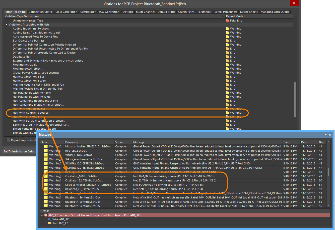
Primarily, the Messages panel includes the results of project compilation and lists any warnings and/or errors that the Compiler may have found while checking the design for electrical and drafting integrity. What this means is that the entries in the Messages panel will be directly affected by the error reporting levels and/or connection matrix defined in the Error Reporting tab of the Project Options dialog as shown in the image below.
The Messages panel also provides warning/error/status information for many other features in the software. These include DRC, Signal Integrity analysis, Mixed-Signal simulation, and when using the Situs Autorouter.
The information contained within a message can be broken down into several distinct areas:
- Class - the class of the message is dependent upon the Source. For example, messages regarding the compiler include Info, Warning, Error, and Fatal Error classes, while messages regarding the Autorouter include Routing Status and Situs Event.
- Document - the source document of the message.
- Source - the server or engine that performed the task when the warning/error/violation was encountered (e.g., the Compiler).
- Message - the message itself.
- Details - displays detailed information regarding the selected message, e.g., missing data.
Right-click Commands
The right-click menu provides the following commands:
- Group By - select from the following choices to sort the messages:
- Source
- Class
- Document
- None
- Cross Probe - cross probe from the selected message in the panel to the object responsible for the message in the associated document.
- Cross Probe Next Message - cross probe the next message in the panel.
- Cross Probe Previous Message - cross probe the previous message in the panel.
- Waive Violation - waive the selected violation(s). Launches the Waived Violation Info dialog, in which you can document information about waived violations, including when the violation was waived, who waived the violation, and the reason for waiving the violation.
- Place Specific No ERC for this violation - place a specific No ERC for this violation in the schematic.
- Clear All - clear all messages that are currently displayed in the panel.
- Clear Selected - clear all selected messages from the panel.
- Clear Class - clear all messages from the panel that are of the same class as the currently selected message.
- Save - save the current list of messages in the panel to a file. After launching the command, the Save Message List To File dialog appears. Use this dialog to browse to a particular destination in which to save the file and to give the file a new name (if required).
- Save Selection - save selected messages in the panel to a file. After launching the command, the Save Message List To File dialog appears. Use this dialog to browse to a particular destination in which to save the file and to give the file a new name (if required).
- Export To Report - select to export all listed messages to a report.
- Copy - copy the selected messages to the Windows clipboard.
- Print - preview and print a report containing all messages currently listed in the panel.
When cross-probing (where applicable) from a message in the panel to the offending object(s) on the affected document, you will either be taken directly to the object on the associated document, or indirectly, depending on the particular source of the message.
Tips
- Not all messages can be cross probed. You can only cross probe from a message if it has a valid (existing) associated document, which is specified in the Document field of the message.
- When cross-probing to a PCB document:
- Ensure that the relative PCB document is the active document in the design editor window, otherwise cross probing will occur but you will not jump to it in the document.
- The offending object(s) will be automatically zoomed and centered (where possible) in the design editor window. Highlighting options available from the PCB panel have no affect on the display.
- When cross-probing to a schematic document:
- The document will be made active if it is not already.
- The visual display of a cross-probed object on a schematic document in the design editor window is dependent upon the highlighting options defined on the System - Navigation page of the Preferences dialog. These options include zooming, selecting, and dimming; the latter causes all other objects on the document to become dimmed leaving only the offending object fully visible.
- The filtering applied when cross probing from the Messages panel is temporary. Clicking inside the design editor window will clear the filter so that you are not prevented from selecting or editing design objects that fall outside the scope of the filter.
- The extent of 'dimming' applied when the dimming option is enabled can be manually adjusted using the Mask and Dim Settings region on the View Options tab of the View Configuration panel.
- Data may be sorted by any column by clicking on the header for that column. Click once to sort in ascending order; click again to sort by descending order.
- You can change the order in which columns of data are displayed. To move a column, click on its header and drag it horizontally to the required position. A valid position is indicated by the appearance of two blue positional arrows.
- Clearing messages does not necessarily mean the messages have been resolved. The same unresolved messages will be listed after performing the same command that led to the messages being generated initially. Message clearance is a visual aid when resolving errors in the design that allows you to manually remove messages as you feel they have been resolved. The initial command must be launched again to obtain an up-to-date picture of any violations that still exist.
- Clearing all messages is particularly useful when you do not want any previous messages from any other sources to confuse warnings and errors that have been generated from the last command. In some cases, running a command will automatically clear the Messages panel prior to populating it with a fresh list of messages that are generated as a consequence of running that command.
- With respect to PCB/Compiler/Comparator-specific messages, if the associated document is closed, the corresponding message entries will be automatically cleared from the panel. For example, if you run a DRC Check on a PCB document, any violation messages listed in the Messages panel for that document will be cleared from the panel if the document is closed.