
KB: Board Cutout not in Gerber output
Created: March 25, 2021 | Updated: August 12, 2021
Starting in version: 18
Up to Current
Board cutouts are not exported in Gerber file export. This article shows how to generate outlines for the cutouts onto a mechanical layer for documentation and inclusion in the fabrication output files.
Solution Details
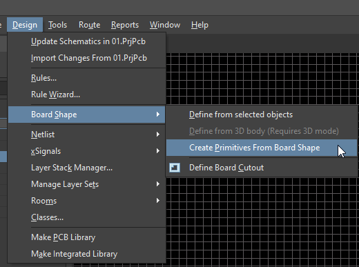
Board cutouts do not naturally export when Gerber files are generated. In order to have cutouts displayed in Gerber export, it is necessary to first perform the following steps to create outlines as follows:1. Create an outline around the board cutout by using: Design ► Board Shape ► Create Primitives from Board Shape.
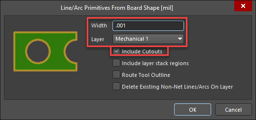
2. With the Line/Arc Primitives from Board Shape panel, set the width to be a small value (such as .001mil) and set the layer to be a Mechanical Layer.
3. Enable the option Include Cutouts and select 'OK' to confirm. This will generate an outline around the board and all cutouts.
4. Generate your Gerber output files and make sure that to enable the Mechanical Layer, specified in step 2 above, to have the outlines exported in the mechanical Gerber layer.
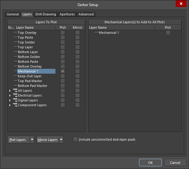
This will generate a Gerber file for Mechanical Layer that represents the cutouts.
A related topic for generating the route tool path for the board outline and cutouts in the NCDRILL file can be found in our documentation here.