What approach do I use for defining design constraints?
Altium Designer suggests two distinct approaches to defining design constraints: the PCB Rule and Constraints Editor dialog (described on this page) and the Constraint Manager.
The Constraint Manager is available in a PCB design project only if the Constraint Management option was enabled in the Create Project dialog when this project was created. Note that:
- If the Constraint Manager was enabled for the PCB project, the PCB Rule and Constraints Editor dialog is not available in the PCB editor.
- If the Constraint Manager was not enabled for the PCB project, only the previous approaches to define design constraints (use of design directives and the PCB Rule and Constraints Editor dialog) can be used.
To quickly check which approach to design constraint management is used in the current PCB project, open the project's PCB document, click the Design main menu, and check which command is available:
- Constraint Manager – the Constraint Manager is used for this project.
- Rules – the PCB Rule and Constraints Editor dialog is used for this project.
The PCB Editor uses the concept of Design Rules to define the requirements of a design. Design requirements are applied using an elegant - target these objects and apply those requirements - approach. Design rules collectively form an 'instruction set' for the PCB editor to follow. They cover every aspect of the design – from routing widths, clearances, plane connection styles, routing via styles, etc., and many of the rules can be monitored in real-time by the online Design Rule Checker (DRC), and you can also run a batch test at any time to generate a DRC report. Rules are defined independently of the objects.
Design rules target specific objects and are applied in a hierarchical fashion; for example, there is a clearance rule for the entire board, then perhaps a clearance rule for a class of nets, then perhaps another for one of the pads in a class. Using the rule priority and the scope, the PCB editor can determine which rule applies to each object in the design.
A rule targets the objects using a keyword-driven query language, which can range from broad identifiers, such as NetClass or All, right down to a tightly defined query that precisely targets a tricky, situation-specific, design requirement.
With a well-defined set of design rules, you can successfully complete board designs with varying and often stringent design requirements. Additionally, since the PCB Editor is rules-driven, taking the time to set up the rules at the beginning of the design will enable you to effectively get on with the job of designing, safe in the knowledge that the rules system is working hard to ensure that success.
Fundamentals of the PCB Rules System
The rules system built into the software's PCB editor has several fundamental features that set it apart from most other design rule systems employed by other PCB editing environments:
- Rules are separate from the objects – a rule is not added as an attribute of an object, but is rather added to the overall rule set and then scoped to apply to that object. This allows rules to be applied to multiple objects and modified or applied to different objects, which would otherwise be painful to do if having to change rule attributes at the individual object level.
- Rules are targeted (scoped) by writing a query – instead of using a set of fixed, predefined rule scopes, a flexible query system is used to define the objects to which a rule is applied. This gives precise control over the target of each and every design rule.
- Rules for any design situation – multiple rules of the same type can be defined and targeted to different sets of objects, allowing complete control over the definition of board constraints. For example, different width rules can be defined to route nets at different widths on different layers.
- Each rule has a priority – any design object can be targeted by multiple rules of the same type, catering for general and more specific situations. To resolve any rule contention, the rule priority is used. The system simply goes through the rules from highest to lowest priority and picks the first one whose scope expression(s) match the object(s) being checked.
- There are two types of rules – unary rules (rules that define the required behavior of an object) and binary rules (rules that define the interaction between two objects).
Design rules in Altium Designer are defined and managed from within the PCB Rules and Constraints Editor dialog as described on this page. As an alternative approach for managing the design constraint rules, the document-based Constraints Editor ([Constraints] document tab) can be used.
Defining and Managing Design Rules
The PCB Rules and Constraints Editor dialog is accessed by choosing the Design » Rules command from the main menus.
Is the
Rules command not in the
Design menu? Check if you have the
PCB Rules and Constraints Editor dialog available –
learn more.
The PCB Rules and Constraints Editor dialog has two sections:
- The tree on the left lists the different rule categories. Expand a category to display the individual rule types available. Expand a rule type to display all rules of that type that are currently defined.
- The right side of the dialog presents information in relation to what is currently selected in the tree – either a summary of defined rules of the selected rule type or category, all defined rules for the entire system, or, if an actual rule is selected, the constraints for that rule.

The PCB Rules and Constraints Editor dialog – command central for managing design rules.
Options and Controls of the PCB Rules and Constraints Editor DialogExpand折りたたむ
The dialog is composed of a static pane on the left and the main editing region on the right that changes dynamically with the selection on the left. The dialog’s search engine allows it to be used in a straightforward search mode by entering the relevant Name, Type, Category, or Attribute keyword(s) in the main Search field.
Left-Hand Pane
In the folder-tree pane on the left side of the dialog, each of the supported design rule categories, and types thereof, are listed under the Design Rules folder. The following rule categories and types are supported in Altium Designer:
- Electrical - this category offers the following rule types: Clearance, Short-Circuit, Un-Routed Net, Un-Connected Pin, and Modified Polygon.
- Routing - this category offers the following rule types: Width, Routing Topology, Routing Priority, Routing Layers, Routing Corners, Routing Via Style, Fanout Control, and Differential Pairs Routing.
- SMT - this category offers the following rule types: SMD To Corner, SMD To Plane, SMD Neck-Down, and SMD Entry.
- Mask - this category offers the following rule types: Solder Mask Expansion and Paste Mask Expansion.
- Plane - this category offers the following rule types: Power Plane Connect Style, Power Plane Clearance, and Polygon Connect Style.
- Testpoint - this category offers the following rule types: Fabrication Testpoint Style, Fabrication Testpoint Usage, Assembly Testpoint Style, and Assembly Testpoint Usage.
- Manufacturing - this category offers the following rule types: Minimum Annular Ring, Acute Angle, Hole Size, Layer Pairs, Hole To Hole Clearance, Minimum Solder Mask Sliver, Silk To Solder Mask Clearance, Silk To Silk Clearance, Net Antennae, and Board Outline Clearance.
- High Speed - this category offers the following rule types: Parallel Segment, Length, Matched Lengths, Daisy Chain Stub Length, Vias Under SMD, Maximum Via Count, and Max Via Stub Length (Back Drilling).
- Placement - this category offers the following rule types: Room Definition, Component Clearance, Component Orientations, Permitted Layers, Nets to Ignore, and Height.
- Signal Integrity - this category offers the following rule types: Signal Stimulus, Overshoot - Falling Edge, Overshoot - Rising Edge, Undershoot - Falling Edge, Undershoot - Rising Edge, Impedance, Signal Top Value, Signal Base Value, Flight Time - Rising Edge, Flight Time - Falling Edge, Slope - Rising Edge, Slope - Falling Edge, and Supply Nets.
Click on the root folder to access a summary listing in the main editing region of the dialog of all specific rules that have been defined for all design rule types across all categories.
Click on a category folder to access a summary listing of all specific rules that have been defined for all associated design rule types of that category.
Click on a rule type folder to access a summary listing of all specific rules that have been defined for that type.
Click on the entry for a specific rule in the folder-tree pane (or double-click on its entry in a summary list) to access controls for managing its definition.
Right-click Menu
The following commands are available from the right-click menu for the left-hand pane:
- New Rule - use this command to create a new rule of the currently selected rule type. The new rule will be added to the folder-tree and will also appear in the summary list for that rule type. The rule name will appear bold to distinguish it as being new and yet to be 'applied'.
When a new rule is added, it will initially be given a default name based on the specific type of rule. For example, if you add a new Clearance rule, the default name will be Clearance. If this default naming is not changed, adding another new rule of the same type will result in the same rule name with an incremented numerical suffix (i.e. Clearance_1, Clearance_2, etc.).
When a new rule is created for a particular rule type, it is automatically given priority 1 (the highest priority). If any other rules of that type exist, their priorities will be shifted (lowered) by one, accordingly. They are then considered to be modified – even though they may not have been specifically modified at the scope/constraint level. All such existing rules of that type will therefore be displayed in the modified state (bold with an asterisk).
- Duplicate Rule - use this command to quickly create an identical copy of the currently selected existing rule. The duplicate rule will be named the same as the original with the addition of a suffix (e.g., _1) to distinguish it. Its definition (scope, constraints, etc.) will be identical to that of the original.
In terms of priority, the duplicate rule will be given the next priority below that of the original rule. For example, if the original rule has priority 1, the duplicate will be given priority 2.
- Delete Rule - use this command to delete the specific rule that is currently selected in the folder tree. The rule name will appear bold with strike-through highlighting to distinguish it as being a deletion that has yet to be 'applied'.
Many rule types have default rules created when a new PCB document is created. In a similar fashion, if all specific rules for one of those rule types are deleted, the default rule will be re-added automatically.
- Report - use this command to generate a report of currently defined design rules. The report can be for all rule categories, a specific rule category, or a specific rule type, depending on the selected entry in the folder-tree. The Report Preview dialog will appear with the appropriate report already loaded. Use this dialog to inspect the report using various page/zoom controls before ultimately exporting it to a file or printing it.
- Export Rules - use this command to export your favorite rule definitions to a file. The Choose Design Rule Type dialog will appear. Select the rule types you wish to export and click OK. The Export Rules to File dialog will then appear from where you can determine where and under what name the exported PCB Rule file (*.rul) is to be stored.
- Import Rules - use this command to import rule definitions from a previously saved rule file. The Choose Design Rule Type dialog will appear. Select the rule types you wish to import and click OK. The Import File dialog will then appear from where you can browse to and open the particular PCB Rule file (*.rul) you wish to import.
When importing, if rules of a chosen type already exist, the option will be given to clear the existing rules prior to import. Clicking Yes results in all existing rules of that type being deleted and subsequently replaced with those in the .rul file. Clicking No will keep the existing rules. However, if existing rules and imported rules have the same name, the imported rules will overwrite the existing ones.
Main Editing Region
This region of the dialog changes dynamically with what is currently selected in the left-hand pane. It presents two different views:
- Summary Listing - if the root Design Rules folder or any of the child rule categories or type folders are clicked in the left-hand pane, this region will present a summary listing of all defined rules or all rules of the selected category or type. Each rule is listed in terms of the following:
- Name - the name of the rule.
- Priority - the rule's current priority.
- Enabled - whether the rule is currently enabled or disabled (click to toggle this state).
A disabled rule will be grayed out in a summary listing.
- Type - the type of rule.
- Category - the rule category to which it belongs.
- Scope - the scope of the rule (i.e. to which object(s) it applies).
- Attributes - the constraint attributes that have been defined for the rule.
The summary listings also provide the following buttons:
- New Rule - click this button to create a new rule of the type currently selected in the folder-tree pane of the dialog.
- Delete Rule(s) - click this button to delete the specific rule(s) currently selected in the displayed list. A deleted rule's name will appear bold with strike-through highlighting to distinguish it as being a deletion that has yet to be 'applied.'
Multiple rules can be selected in a list using standard multi-select techniques (Ctrl+click, Shift+click).
- Duplicate Rule - click this button to quickly create an identical copy of the currently selected existing rule in the displayed list.
- Report - click this button to generate a report containing all design rules in the currently displayed list. The Report Preview dialog will appear with the report already loaded. Use this dialog to inspect the report using various page/zoom controls before ultimately exporting it to a file or printing it.
The Report option is also available from the right-click context menu for the region.
- Rule Definition - if a specific rule is selected in the left-hand pane, this region will present the following controls for defining that rule.
- Name - the current name of the rule. This can be changed as required.
- Comment - this field displays any comment added for the rule, for example, a meaningful description of what the rule is being used for.
- Unique ID - the unique identifier for the rule. Every rule is itself a design object, and hence a tangible piece of data. The use of an ID ensures uniqueness. Where the Unique ID really comes into play is for a rule that has been created within the schematic domain. When adding design rule parameters to objects on a schematic, a unique ID is given to each rule parameter. The same IDs are given to the corresponding design rules that are created in the PCB. With this Unique ID, the constraints of a rule can be edited on either the schematic or PCB side and the changes pushed through upon synchronization.
- Test Queries - click to open the Test Queries Result dialog that shows the number of objects affected by the rule taking into account rule specializations you defined. This allows you to see if there are objects that respond to the query and also to check that the set of objects affected by the filters and rules is what you desire.
- Rule Scoping Controls - this region provides controls for determining the scope of the rule in terms of the objects it applies to or between. See the Rule Scoping Controls section below for more detail on using the controls in this region.
- Constraints - this region of the dialog presents the constraints applicable to the type of rule being edited. Use the various controls to configure these constraints as required. Press F1 over the constraints region to access a page for that rule type, within the PCB Design Rule Types area of the documentation.
If there is a syntax error with a scoping query, or if a constraint for the rule is invalid, the rule name, the rule type, and the rule category will appear in red in the folder-tree. In addition, the rule name will also appear in red in a summary listing. A warning message will also appear should the designer attempt to close this dialog. A rule scope that has a syntax error can greatly slow the Online and Batch DRC analysis so be sure to resolve any rule scopes that are not syntactically correct.
Changes made to existing rule definitions are highlighted in both the folder-tree pane and the applicable summary lists. Such entries are distinguished by the rule name becoming bold and an asterisk displayed to the right of the name.
Rule Scoping Controls
When defining the scope of a design rule - the extent of its application - you are essentially building a query to define the member objects that are governed by the rule. Use the options available in the dialog to build the query required. Depending on whether the rule is unary or binary, you will need to define one or two scopes.
For a unary design rule, controls will be provided to define a single rule scope. Use the options available in the Where The Object Matches region to help build the query expression, which will be presented in the region to its right. For a binary design rule, controls for Where The First Object Matches and Where The Second Object Matches will be provided to define both rule scopes. Use the available drop-downs of each to help build the query expression.
Controls are the same, whether defining one or two rule scopes and are detailed in the following sections.
Where The Object Matches
- Scoping Option - use the drop-down(s) to select your desired filters:
- All - generate a scope query that targets all design objects.
- Net - generate a scope query that targets all objects in a specific net. An additional drop-down appears from which you can select the desired net from a list of available choices, including No Net.
- Net Class - generate a scope query that targets all objects in a specific net class. An additional drop-down appears from which you can select the desired net class from a list of available choices, including All Nets.
- Layer - generate a scope query that targets all objects on a specific layer. An additional drop-down appears from which you can select the desired layer from a list of available choices.
- Net and Layer - generate a scope query that targets all objects in a specific net and on a specific layer. Two additional drop-downs appear from which you can select the desired net and layer.
- Custom Query - gives you the ability to write your own query.
- Textbox (Query region) - reflects the current query expression created for the rule scope.
If you are conversant with the Query Language, you can enter a query expression directly in the region. You can also paste a query expression from your favorite editor directly into the region or copy a query expression into an external editor, or even to paste the query into the second scope of a binary rule. This is especially useful if the two scopes are complex and differ only slightly.
When the Custom Query option is selected, the following two new buttons appear:
- Query Helper - use to access the Query Helper dialog. The underlying query engine analyzes the PCB design and lists all available objects along with generic keywords for use in queries.
- Query Builder - use to access the Query Builder dialog, which enables you to create a query for targeting specific objects in the design document.
The Query Builder dialog is a simpler method of constructing a query, using sensitive condition types and values that allow you to build only using relevant 'building blocks'. For advanced query construction with full keyword specification and operator syntax, use the Query Helper dialog.
Query Expression Operator Precedence
Brackets have the highest precedence within an order of precedence that has been defined for the various operators, and which determines how queries are interpreted by the software (whenever you have not provided brackets). The sequence of this order is as follows:
Brackets
Not
^, *, /, Div, Mod, And
+, -, Or, Xor
=, <>, <, >, <=, >=
&&, ||
This order of precedence is similar to that used in Pascal type languages. Ambiguities are resolved by working from left to right. Parentheses are evaluated from inside to outside and equal levels are evaluated left to right.
It is highly advisable to use brackets whenever there is any possibility whatsoever that the query might not be correctly interpreted. Generous usage of brackets removes doubt and makes the resulting queries easier for others to read.
Additional Buttons
The following additional controls are provided at the bottom of the dialog:
- Switch to Document View - click to open the Constraints Editor, which is an interactive Rules document.
- Rule Wizard - click to run the Design Rule Wizard, which takes you through the process of creating a new design rule.
The Rule Wizard button will be unavailable if there are modifications to existing rules that have not yet been 'applied'.
- Priorities - click to access the Edit Rule Priorities dialog from where you can manage the priorities of multiple rules of the same rule type.
Multiple rules of the same type can be set up. It may arise that a design object is covered by more than one rule with the same scope. In this instance, a contention exists. All contentions are resolved by the priority setting. The system goes through the rules from highest to lowest priority and picks the first one whose scope(s) match the object(s) being checked.
- Create Default Rules - click to regenerate the default set of design rules for the PCB. If you remove rules, you can get your default rule set back by clicking this button.
If a default rule has been modified, it will not reset it or replace it.
- Apply - click to apply the design rules.
Default Design Rules
When a new PCB document is created, it includes a number of default rules, which must exist for the correct functioning of the Design Rule Check system. If a default rule is deleted, it is automatically re-created when the PCB Rules and Constraints Editor is closed. If there are design rules that you do not wish to use, the correct approach to managing these rules is to disable them.
To disable a rule, toggle the corresponding Enable option for that rule in one of the summary lists on the right-hand side of the PCB Rules and Constraints Editor dialog. A disabled rule appears 'grayed-out'. Learn more about disabling design rules.
 Use the Enable option to disable a rule that you do not need. A disabled rule appears 'grayed-out'.
Default rule values are internally defined in mils and may have values that do not suit your designs. To use your own default rules and values, you can:
- create and use a project template, or
- create a suitable empty board file with the rules configured as you require, and take a copy the board for your new project, or
- export your set of template rules to a PCB Rule file (
*.RUL), then import those rules into your current board design. Learn more about exporting and importing design rules.
Creating a New Rule
To add a new design rule from within the PCB Rules and Constraints Editor dialog, navigate to and select the required rule type within the left-hand tree then click the New Rule button below the rule summary list, or right-click over the required rule type then select New Rule from the context menu.
The new rule will be added to the folder tree and will also appear in the summary list for that rule type.

Example creation of a new PCB design rule.
When a new rule is added, it will initially be given a default name based on the specific type of rule. If a rule with that name already exists, it will be given an incremented numerical suffix (e.g., Width_1, Width_2, etc.).
To access the scope and constraint attributes for the rule, either click on the entry for the rule in the folder-tree pane or double-click on its entry in a summary list. The main editing window of the dialog will change to give access to the controls for defining the scope and constraint attributes for that rule.

Accessing the detailed controls for the rule, including scope and constraints.
To fully define the new rule:
- Give the rule a meaningful name to make it identifiable.
- Define the scope of the rule by selecting scoping options from the drop-down(s), or by entering a query (or queries for a binary rule).
- Set the constraints of the rule.
- Set the priority of the rule.
Using the Rule Wizard to Create a New Rule
A new rule can also be created using the Design Rule Wizard. Access is made directly using the Design » Rule Wizard command or by clicking the Rule Wizard button at the bottom of the PCB Rules and Constraints Editor dialog.
Use the pages of the Wizard to create a new design rule. The steps are:
- Choose the required rule type and giving it a meaningful name (and comment if required).
- Define the scope of the rule. You will have the opportunity to further enhance scoping through an incarnation of the Query Builder that is built into the Wizard.
- Set the rule priority.
If the Launch main design rules dialog option is enabled on the last page of the Wizard, the PCB Rules and Constraints Editor dialog will open upon clicking the Finish button. This dialog can be used to edit the constraints for your newly-created rule.

Use the Design Rule Wizard to streamline rule creation.
Duplicating an Existing Rule
To quickly create an identical copy of an existing rule, use the duplicate feature. This feature can be accessed in two ways:
- Use the tree on the left to navigate to the required existing rule, right-click then choose Duplicate Rule from the context menu.
- Navigate to the specific rule type in the tree on the left, select the rule to be duplicated in the summary list on the right, then click the Duplicate Rule button below the list.

Streamline creation of similar rules using the rule duplication feature.
The duplicate rule will be named the same as the original, with the addition of a suffix (e.g., _1) to distinguish it. Its definition (scope, constraints, etc.,) will be identical to that of the original. In terms of priority, it will be given the next priority below that of the original rule. So, for example, if the original rule has priority 1, the duplicate will be given priority 2.
Creating a Rule from the PCB Filter Panel
Since a design rule is scoped to apply to a target set of design objects, it can be easier (and faster) to first identify those objects then create a design rule that targets them. The PCB Filter panel provides the facility for creating a design rule, the scope of which uses the currently defined query expression in the panel. So rather than struggling to visualize what your query expression might target, use the PCB Filter panel to test and tweak a query expression until only those required objects are filtered. By then creating a rule that uses that query expression, you are guaranteed to be targeting the correct set of objects.
To add a new design rule:
- Click on the Create Rule button. The Choose Design Rule Type dialog will appear. This dialog lists each of the rule categories and rule types that are available in the PCB document.
- Choose the type of rule to be created then click OK (or double-click directly on the entry).
- The PCB Rules and Constraints Editor dialog will appear. A rule of the chosen type is created and the main editing window for the rule is displayed, ready to define specific constraints for the rule. The scoping option for the rule is set to Custom Query, and the query expression from the PCB Filter panel is entered into the query region accordingly.
- Make changes to the rule's name and constraints as necessary. Also, change its priority if needed (it will be given the highest priority by default).

Create a new design rule directly from the PCB Filter panel – the filter query expression is used as the scope for the rule.
Reusing Past Query Expressions
Over time, a number of useful query expressions will be constructed in the course of laying out various boards. Typically, you will want to apply and re-apply the same queries, not only in the same design but across different designs. To allow this, the PCB Filter panel supports the notion of Historical and Favorite queries.
As a query is entered and applied from the panel, it will be added to a query 'history list'. In addition, that query can be added to a query 'favorites list' by clicking the Add To Favorites button. Use the History and Favorites buttons in the panel to access the corresponding tabs of the same name within the Expression Manager dialog to see these lists.

Access a history of applied query expressions and build a listing of favorite expressions to be reused time and again.
To use an expression in either list, double-click on its entry or select its entry and click the Apply Expression button. The Expression Manager dialog will close and the expression will be loaded into the Filter region of the PCB Filter panel.
This functionality streamlines (and expedites) the creation of rules with requisite scoping – retrieve a historical or favorite query expression, check that it still targets the required object set (apply the filter) then create a rule that utilizes that expression in its scoping, as detailed in the previous section.
Scoping a Design Rule
Altium Designer's PCB editor is a rules-driven environment. Design requirements are enforced through a well-defined set of design rules that collectively define the constraints for the board. Design rules target specific objects within a design. For the PCB rules system to know for which objects a given rule applies, it needs to know the scope of that rule, i.e. the extent of its application. Scoping, or targeting the rule, is performed in the PCB Rules and Constraints Editor dialog.
The default design rules, or a new rule that is added, will have the default rule scope of All, meaning it will be applied to all objects on the board. Using the drop-down, a simple rule scope can be quickly configured.

Set the scope of a design rule to define its application to the design objects.
Rather than being restricted to a predefined list of possible target options, each design rule can be more tightly scoped by writing what is called a Query.
To enter a query, set the first Where the Object Matches drop-down to Custom Query. It will display the query currently being used by the rules engine for this rule based on the current drop-down settings.
A query is essentially an instruction to the software that defines the set of design objects to be targeted. Queries are written using query keywords. In the same way that a query can be written in a Filter panel to find a specific set of objects, a query also can be written to define the objects that each rule targets. An example might be:
InNet('VBAT') And OnLayer('Bottom Layer')
If this query were to be used as the scope for a Width rule, whenever you route the VBAT net and switch to the bottom layer, the track width would automatically change to the width specified as part of that rule's constraints. Also, upon running a design rule check, any VBAT net routing on the bottom layer would have to have the specified width or it would be flagged as a violation.

Scoping the rules is based upon the query system. Use the Custom Query option to see the current query and change it using the query keywords if needed.
Depending on whether the rule is unary or binary, you will need to define one or two scopes respectively.
When changes are made to PCB component designators or polygon names, the references in design rules using custom queries are updated automatically. The queries referencing PCB component designators in design rules are changed when designators are reannotated, updated by an ECO, or manually edited on the board.
Updating rule queries when component designators are changed is available when the PCB.Rules.UpdateQueryOnComponentDesignatorChange option is enabled in the Advanced Settings dialog.
If there is a syntax error with the query, the rule will be deemed invalid and will be highlighted in red in the PCB Rules and Constraints Editor dialog both in the left-hand rule tree and any summary view (rule category or rule type) in which the rule appears. In addition, the text for the rule type and rule category is also presented in red in the left-hand rule tree. So if you have collapsed an area of the rule tree that contains an invalid rule, you will still be alerted to it at a higher level in the hierarchy. A warning message will also appear if you attempt to close the dialog. A rule scope that has a syntax error can greatly slow the Online and Batch DRC analysis process. Be sure to resolve any rule scopes that are not syntactically correct.
Scoping Options
Simple scoping options are provided that allow you to quickly generate scope queries. Select one of the options from the first drop-down field and, if required, use the subsequent drop-down list(s) to select the appropriate target, such as a Net, Layer, Footprint, Package, and so on. The scoping options presented are focused according to rule type.

Quickly create a query using the simple scoping options.
When you scope the rule using the simple scoping options, a query is still created. The query is displayed if you select Custom Query in the first drop-down field.
The Custom Query option enables you to write your own, perhaps more complex but also more specific query. You can type your own specific query for the rule scope directly into the query region to the right. Alternatively, two features are available to help in the creation of logical query expressions. They are the Query Builder and the Query Helper. These can be useful when you are unsure of the syntax of a query or the keywords that are available.

Use the Custom Query option to craft a more complex query expression.
The Query Builder is a simpler method of constructing a query that uses sensitive condition types and values that only allow you to build using relevant 'building blocks'. For advanced query construction with full keyword specification and operator syntax, use the Query Helper.
Scoping a Rule with the Query Builder
Click the  button to open the Building Query from Board dialog, which enables you to create a query for targeting specific objects in the design document by the simple construction of a string of conditional statements.
The left-hand section of the dialog is used to specify the condition(s) required to target the set of objects needed. Each condition is made up of a Condition Type and a Condition Value. Drop-down fields for these populate with entries that are relevant to building a scope for the current rule type and values for the chosen condition type, respectively.
As a condition is defined, a preview of the currently built query is shown in the right-hand section of the dialog. Conditions can be ANDed and/or ORed together, and also precedence incorporated (through the use of brackets/indenting) to refine the target set of objects. When the expression for the query has been defined as required, clicking OK will load the expression into the query region of the PCB Rules and Constraints Editor dialog.
Note that additional opening and closing brackets are added to the start and end of the query expression, respectively, when presented in the PCB Rules and Constraints Editor dialog.

Use the Query Builder to build a logical query expression through a series of conditional statements.
Scoping a Rule with the Query Helper
With the Custom Query option enabled, click the 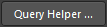 button to access the Query Helper dialog. The underlying Query Engine analyzes the PCB design and lists all available objects, along with generic keywords for use in queries.
Working with the Query Helper is fairly intuitive, even more so when you break it down into three distinct areas as shown in the image below:

Example complex query defined using the Query Helper.
These areas are:
- Query Region – use this region of the dialog to compose a query expression. The expression currently in effect for the rule scope will be made available in this region, by default, when the dialog is accessed. You can type directly within the region; a context-sensitive 'prompt list' of possible keywords or objects will appear as an aid.
- Operators – this region of the dialog provides a range of mathematical and logical operators for use when constructing an expression. Click a button to add that operator at the current cursor location within the query expression in the Query region above.
- Categories, Keywords and Objects – this region of the dialog provides access to available PCB Functions, PCB Object Lists and System Functions, which can be used to create the query expression. Clicking on a sub-category within each of these three areas will display a list of corresponding keywords or objects in the region to the right. Locate the keyword or object to be used in the query string then double-click on its entry; the entry will be inserted at the current cursor location within the query expression in the Query region above.
Use the  button (bottom-left of the dialog) to verify that an expression is syntactically correct. When the expression for the query has been defined as required, clicking OK will load the expression into the query region of the PCB Rules and Constraints Editor dialog.
When using the
Query Helper dialog to construct a query, clicking on a keyword in one of the available lists and pressing
F1, will access the documentation for that particular keyword, within the
Query Language Reference.
Query Expression Operator Precedence
Before leaving this area, it is worth taking a look at the order of precedence in place for the operators used in logical Query expressions. After all, without such knowledge, an expression may not target the objects required.
Brackets have the highest precedence within an order of precedence that has been defined for the various operators, and which determines how queries are interpreted by the software (whenever the user has not provided brackets). The sequence of this order from highest to lowest is as follows:
- Brackets
- Not
- ^, *, /, Div, Mod, And
- +, -, Or, Xor
- =, <>, <, >, <=, >=
- &&, ||
This order of precedence is similar to that used in Pascal-type languages. Ambiguities are resolved by working from left to right. Brackets are evaluated from inside to outside and equal levels are evaluated left to right.
It is highly advisable to use brackets whenever there is any possibility, whatsoever, that the query might not be correctly interpreted. Generous usage of brackets removes doubt and makes the resulting queries easier to read by others.
Rule Prioritization
To simplify the process of defining and managing rules, the idea is to define general rules that cover broad requirements and then override these with specific rules in specific situations. For this to be possible, you need to be able to prioritize the rules in order to indicate which one to use when an object is targeted by multiple rules of the same type.
For example, to specify the most commonly used routing width on the board, define a single rule that applies to every net on the board. This rule can then be overridden for a specific net (or a class of nets for that matter) by adding another rule of the same type, but with a higher priority.
Another example could be the solder mask requirements. Here you would define one mask rule that targets every pad and via on the board, which could then be overridden for the pads in a specific footprint-kind. This footprint-specific rule could further be overridden for a specific pad in that footprint if required.
An important aspect of managing the rules is ensuring that all the priorities are set appropriately. When a new rule is created, it defaults to the highest priority. Use the Priorities button at the bottom of the PCB Rules and Constraints Editor dialog to configure the priorities in the Edit Rule Priorities dialog.

Change rule priorities in the Edit Rule Priorities dialog.
Initially, the dialog will list all rule instances for the rule type that is currently selected in the PCB Rules and Constraints Editor dialog. Use the Rule Type field to change the rule type and list the specific rules defined for that type. The defined rules are listed in order of current priority – from 1 (highest priority) downwards. Select a rule entry and use the Increase Priority and Decrease Priority buttons to move it up or down in the priority order, respectively.
When adding a new rule to a rule type that already contains one or more existing rules, the priority will be set to 1 (i.e. the highest priority).
Multiple rules of the same type can be set up. It may arise that a design object is covered by more than one rule with the same scope. In this instance, a contention exists. All contentions are resolved by the priority setting. The system goes through the rules from highest to lowest priority and picks the first one whose scope expression(s) match the object(s) being checked. There is one exception to this,
multiple Matched Length design rules can be applied to objects, and all rules are applied to those objects.
Modifying Existing Rules
Rules, of course, can be modified at any time. Indeed, to arrive at the final working set of rules often involves a few key refinements here and there. Typically this involves scoping to ensure the target design objects are being 'picked up' by the respective rule(s) as required. Select an existing rule in the PCB Rules and Constraints Editor dialog and make changes as necessary to its scoping and constraint attributes.
Changes made to existing rule definitions are highlighted in both the folder-tree pane and the applicable summary lists. Such entries are distinguished by the rule name becoming bold and an asterisk displayed to the right of the name. The asterisk is used to reflect that the rule is an existing rule that has been modified, rather than a newly-created rule (which is displayed in bold without an asterisk).

Example of an existing rule that has been modified. An asterisk is used to flag the modification, along with the rule name being made bold.
When a new rule is created for a particular rule type, it is automatically given priority 1. If any other rules of that type exist, their priorities will be shifted (lowered) by one accordingly. They are then considered to be modified even though they may not have been specifically modified at the scope/constraint level. All such existing rules of that type will therefore be displayed in the modified state (bold with an asterisk).
Flagging Invalid Rules
If a rule is detected as being invalid by the system – for example, it has an issue with its scoping query expression or a value for a constraint that is not allowed – it will be flagged as being invalid. Such a rule will be highlighted in red within the PCB Rules and Constraints Editor dialog both in the left-hand rule tree, and any summary view (rule category or rule type) in which the rule appears. In addition, the text for the rule type and rule category is also presented in red within the left-hand rule tree. So if you have collapsed an area of the rule tree that contains an invalid rule, you will still be alerted to it at a higher level in the hierarchy. A warning message will also appear if you attempt to close the dialog.

An example of the system flagging an invalid design rule, in this case, an erroneous scope query expression.
Disabling Rules
In the rules-driven environment of the software's PCB editor, it is not uncommon to build up a rather impressive and comprehensive array of rules with which to successfully constrain your boards. For whatever reason along the way, you may wish to disable some rules; perhaps they are not applicable to the board in question or they need to be temporarily disabled to ease the load on the Design Rule Checker (and speed up its performance as a result!). Disabling is a good way of keeping such rules just in case they are needed again in the future.
To disable a rule, toggle the corresponding Enable option for that rule in one of the relevant summary lists on the right-hand side of the PCB Rules and Constraints Editor dialog. A disabled rule also will appear 'grayed-out'.

Example disabled rules, appearing in gray font within a summary list.
Rules can also be disabled/enabled directly from the
PCB Rules And Violations panel. Toggle the rule's associated
On option. This is reflected in the rule's
Enable option in the
PCB Rules and Constraints Editor dialog.
Deleting Rules
To delete a single design rule from within the PCB Rules and Constraints Editor dialog:
- Use the tree on the left to navigate to the required existing rule, right-click then choose Delete Rule from the context menu.
- Navigate to the specific rule type in the tree on the left, then select the rule to be deleted in the summary list on the right. Then click the Delete Rule(s) button below the list.
The rule name will appear bold with strike-through highlighting to distinguish it as being a deletion that is yet to be 'applied'.

Deleting a single rule.
- If a particular design rule is no longer required but might be used again in the future, rather than delete it, it can simply be disabled. Do this by toggling the corresponding Enable option for the rule in one of the relevant summary lists on the right-hand side of the PCB Rules and Constraints Editor dialog.
- Multiple rules can be deleted in a single action from a summary list view. To do so, select the rules to be deleted (standard Shift+click and Ctrl+click shortcuts are supported), then click the Delete Rule(s) button below the list.
- Certain rules must be present for the Design Rule Check system to function; if one of these rules is deleted (so that none of that rule type is present), it will be automatically recreated. Learn more about default design rules.
Many rule types have default rules created when a new PCB document is created. In a similar fashion, if all specific rules for one of those rule types are deleted, the default rule will be re-added automatically the next time the PCB Rules and Constraints Editor dialog is accessed. Alternatively, default rules can be created again by clicking the Create Default Rules button at the bottom of the dialog.
Exporting and Importing Rules
Design rules can be exported from and imported to the PCB Rules and Constraints Editor dialog. This allows you to save and load favorite rule definitions between different designs.
- To export – right-click anywhere within the tree on the left of the dialog and select Export Rules. The
![]() Choose Design Rule Type dialog opens in which you can choose the design rule(s) to export. In the Export Rules to File dialog that opens, you can name the .rul file and choose the location. Exported rules are stored in a PCB Rule file (
Choose Design Rule Type dialog opens in which you can choose the design rule(s) to export. In the Export Rules to File dialog that opens, you can name the .rul file and choose the location. Exported rules are stored in a PCB Rule file (*.rul).
- To import – right-click anywhere within the tree on the left of the dialog and select Import Rules. The
![]() Choose Design Rule Type dialog opens in which you can choose the design rule(s) to import. In the Import File dialog that opens, browse to the .rul file to import.
Choose Design Rule Type dialog opens in which you can choose the design rule(s) to import. In the Import File dialog that opens, browse to the .rul file to import.
When importing, if rules of a chosen type already exist, the option will be given to clear the existing rules prior to import. Clicking Yes results in all existing rules of that type being deleted, subsequently replaced with those in the .rul file. Clicking No will keep the existing rules. However, if existing rules and imported rules have the same name, the imported rules will overwrite the existing ones.
Design Rule Reports
A report of currently defined design rules can be generated from within the PCB Rules and Constraints Editor dialog. The report can cater to all rule categories, a specific rule category, or a specific rule type. A report can be generated by:
- Accessing the required summary list, right-clicking then choosing the Report command from the context menu, or by clicking the Report button below the list.
- Right-clicking over the respective entry in the folder-tree then choosing the Report command from the context menu.
The Report Preview dialog will open with the appropriate report already loaded. Use this dialog to inspect the report using various page/zoom controls before ultimately exporting it to a file or printing it.

Generate a PCB Rules Report.

Generate a PCB Rules Report.
Options and Controls of the Report Preview DialogExpand折りたたむ
- Preview Window - the main region of this dialog presents the preview of the generated report. The report can be manipulated using the various controls below the window and on the right-click menu.
Use the scroll bars to move horizontally or vertically in a zoomed in page.
- Page x of x - the first x is the current page being viewed; the second x is the total number of pages in the report.
- All - click this button to have the page sized to fit within the available preview window. As you resize the dialog (and therefore the preview window), the page will resize to stay fully visible.
- Width - click this button to have the page sized to fit within the horizontal extents of the available preview window. As you resize the dialog (and therefore the preview window), the page will resize to stay fully visible across its entire width.
- 100% - click this button to have the page set to full size (100%).
- % - use this field to zoom in or out. Full size is 100%. Enter a smaller value to see a reduced-scale report. Enter a larger value to see an enlarged-scale report.
Zooming can also be performed using Ctrl+mouse wheel or by using the Page Up and Page Down keys to zoom in and out, respectively.
You can pan around the zoomed view by holding down right-click and dragging the document. Use Shift+mouse wheel or scroll bars to scroll horizontally and the mouse wheel to scroll vertically.
- Page Navigation Controls - this cluster of controls collectively provide another means of navigating the pages of the report. The controls allow you to jump to the first, previous, next and last pages in the document respectively. Alternatively, you can enter the page number directly in the text box and press Enter.
- Export - click this button to access the Export Report From Project dialog where you can save the report with a specific location, name and export format. The following formats are supported:
- Microsoft Excel Worksheet (*.xls)
- Adobe PDF (*.pdf)
- Rich Text Format (RTF) (*.rtf)
- Web Page (*.htm, *.html)
- Web Layer (CSS) (*.htm, *.html)
- JPEG Image File (*.jpg)
- Window Bitmap File (*.bmp)
- TIFF Image File (*.tif)
- Print - click this button to print the report. The standard Print dialog will appear from where you can specify page range and number of copies.
- Open Report - click this button to open a generated report in the application you specified in Export. This button is available only after clicking the Export button.
Right-Click Commands
Some of the above commands are also available on the right-click menu, accessed by right-clicking anywhere within the dialog:
- Print - use this button to print the report. The standard Print dialog will appear from where you can specify page range and number of copies.
- Export - click this button to access the Export Report From Project dialog where you can save the report with a specific location, name and export format. The following formats are supported:
- Microsoft Excel Worksheet (*.xls)
- Adobe PDF (*.pdf)
- Rich Text Format (RTF) (*.rtf)
- Web Page (*.htm, *.html)
- Web Layer (CSS) (*.htm, *.html)
- JPEG Image File (*.jpg)
- Window Bitmap File (*.bmp)
- TIFF Image File (*.tif)
- Copy - use this button to copy the active page to the Windows Clipboard from where it can be pasted into an external application as required.
- Page Width - click this button to have the page sized to fit within the horizontal extents of the available preview window. As you resize the dialog (and therefore the preview window), the page will resize to stay fully visible across its entire width.
- Whole Page - use this command to have the page sized to fit within the available preview window.
- Zoom In - use this command to incrementally zoom in on the report.
- Zoom Out - use this command to incrementally zoom out on the report.
Defining Rules on the Schematic
Design constraints (rules) can be defined prior to PCB layout by adding Parameter Set directives to the schematic source document(s) with configured rule(s). The scope of the corresponding PCB design rule, created when the design is transferred to the PCB document, is determined by the nature of the object to which the parameter is assigned. The following table summarizes the schematic parameter-to-PCB rule scope options that are supported.
| Add a rule to a... |
From... |
For a PCB Rule Scope of... |
| Wire |
the Properties panel (when browsing the properties of the selected parameter set object), after placing a Parameter Set object on the wire using the Place » Directives » Parameter Set command. |
Net |
| Bus |
the Properties panel (when browsing the properties of the selected parameter set object), after placing a Parameter Set object on the bus using the Place » Directives » Parameter Set command. |
Net Class |
| Harness |
the Properties panel (when browsing the properties of the selected parameter set object), after placing a Parameter Set object on the harness using the Place » Directives » Parameter Set command. |
Net Class |
| Blanket |
the Properties panel (when browsing the properties of the selected parameter set object), after placing a Parameter Set object on the edge of the blanket using the Place » Directives » Parameter Set command. Include a class with the required name, to create a net class for all nets covered by the blanket, which will then be used for the rule scope. |
Net Class |
In each case, the method of adding a rule-based parameter is the same:
- Add a parameter as a rule.
- Select which rule type to use.
- Configure the constraints for the chosen rule type.
When adding design rule parameters to objects on a schematic, a unique ID is given to each rule parameter. The same IDs are given to the corresponding design rules that are created on the PCB. With this Unique ID, the constraints of a rule can be edited on either the schematic or PCB side, and the changes pushed through upon synchronization.
Checking Rule Application
Depending on the board design, a fair number of design rules may need to be defined with scopes that range from the very simple to the very complex. It is a good idea to check that the rules defined do indeed target their intended objects. Care at the rule definition stage can save wasted time and effort tracing violations caused through incorrect rule scoping.
There are essentially two methods for verifying rule scopes – either by selecting design objects and interrogating the rules that currently apply to them or by taking a rule (in different locations or the software) and observing which objects fall under its scope.
From an Object's Perspective
For any placed object in the current design, you can quickly access information about which unary design rules apply to that object. Position the cursor over the object, right-click then select Applicable Unary Rules. All defined design rules that could be applied to the selected object are analyzed and listed in the Applicable Unary Rules dialog.

Design rules applicable to a single example design object – unary rules.
Each rule listed in the dialog will have either a check ( ) or a cross (
 ) next to it. A check indicates the rule with the highest priority out of all applicable rules of the same type; this is the rule currently applied. Lower priority rules of the same type are listed with a cross next to them, indicating that they are applicable but, as they are not the highest priority rule, they are not currently applied.
Any rules that would apply to the object but are currently disabled would also have a cross next to them and would appear using strike-through highlighting.
In a similar fashion, you also can access information about the binary design rules that apply between two placed objects in a design. Position the cursor over any object, right-click then select Applicable Binary Rules. Follow the prompts to select two objects in the design. The Applicable Binary Rules dialog will then open and display all binary design rules that apply between those objects.
If the two chosen objects do not have any binary rules applied to them, the Binary version of the Applicable Rules dialog will not open.

Design rules applicable between two example design objects – binary rules.
From a Rule's Perspective
Checking via the PCB Rules And Violations Panel
You can also quickly see what objects a particular rule applies to from the PCB Rules And Violations panel. The panel lists all currently defined rules for the design. All rules can be viewed or you can browse specifically by rule type – provided at least one rule of any given type has been defined for the active design. As you click on a specific rule in the Rules region of the panel, filtering will be applied using the rule as the scope of the filter. Only those design objects that fall under the scope of the rule will be filtered. By employing the Mask (or Dim) highlighting feature, you can quickly see the resulting objects targeted by the rule.

An example of using the PCB Rules And Violations panel to check which objects a selected rule applies to.
If the highlighting method in the dialog has been set to
Mask, adjust the level of masking applied to objects not falling under the scope of the active filter by using the
Masked Objects slider bar accessed from the
Mask and Dim Settings section on the
View Options tab of the
View Configuration panel. If the highlighting method in the dialog has been set to
Dim, adjust the level of dimming applied to objects not falling under the scope of the active filter by using the
Dimmed Objects slider bar also available from this section of the panel.
Using the PCB Rules And Violations panel to interrogate which objects a rule applies to is particularly useful when creating a query for a rule’s scope(s) since a rule can be edited directly from the panel and therefore, the query can be 'tweaked' until the desired objects are captured by the scope(s).
To edit the scope(s) for a rule as well as its constraints, either double-click on the rule's entry in the panel or right-click and choose Properties from the context menu. The relevant Edit PCB Rule dialog will appear from where the changes can be made.
The controls offered by the dialog and its banner text will vary depending on the type of design rule being edited.

Rules can be edited directly from the PCB Rules And Violations panel, allowing you to further refine rule scoping and/or constraints on the fly.
Checking via the PCB Rules and Constraints Editor Dialog
The PCB Rules and Constraints Editor dialog includes a query testing facility, allowing you to quickly see what objects a particular rule applies to. Click the  button at the top-right of the dialog for the rule you want to test. The Test Queries Result dialog will appear. This dialog reflects the number of objects falling under the scope of the expression, how many are applicable to the current rule, and how many are applicable based on the rule's current priority (where multiple applicable rules exist). By clicking on a link to the right, you can quickly filter to see the applicable objects in each case directly in the design space. Use the Mask drop-down to select Normal, Mask or Dim depending on how you want the affected objects to be highlighted in the PCB document. If Zoom is checked, the PCB document will also zoom into the affected components.

Quickly view the objects captured by a rule's scoping expression using the Test Queries feature.
