
Working with a Radial Dimension Object on a PCB in Altium Designer
Parent page: PCB Objects
 A placed Radial Dimension.
Summary
A radial dimension is a group design object. It allows for the dimensioning of a radius with respect to an arc or circle. The dimension can be placed either internally or externally, in relation to the circumference of the arc/circle.
Availability
Radial dimension objects are available for placement in the PCB Editor only. Use one of the following methods to access a placement command:
- Choose Place » Dimension » Radial from the main menus.
- Locate and use the Radial command (
 ) on the Active Bar.
- Click the button on the Place Dimension drop-down (
 ) of the Utilities toolbar.
 - Right-click in the workspace then choose the Place » Dimension » Radial command from the context menu.
Placement
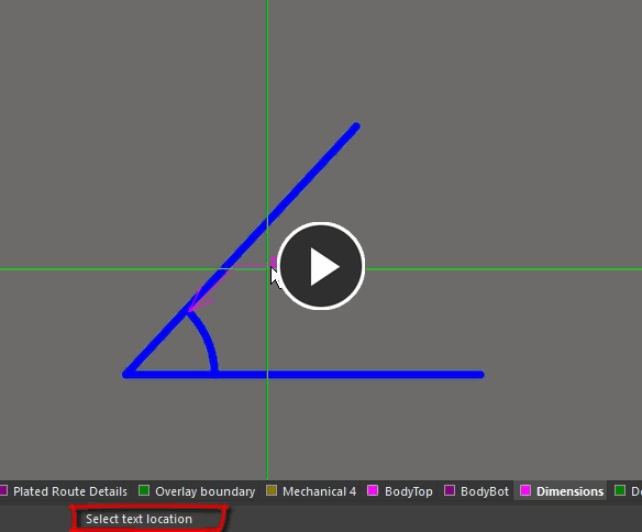
After launching the command, the cursor will change to a cross-hair and you will enter dimension placement mode. Placement is made by performing the following sequence of actions:
- Position the cursor then click or press Enter to anchor the dimension to the desired arc or circle.
- Move the dimension's arrow pointer to the desired location around the arc or circle. The arrow can be placed either inside or outside and movement is in accordance with the Angular Step value in the Radial Dimension mode of the Properties panel. When the required position has been attained, click or press Enter to lock the arrow in place.
- The text can now be initially positioned in relation to the tail of the arrow pointer. Move the text into the required position then click or press Enter to complete placement.
- Continue placing further radial dimensions or right-click or press Esc to exit dimension placement mode.
Additional actions that can be performed during placement are:
- Press the + and - keys (on the numeric keypad) to cycle forward and backward through all visible layers in the design to change placement layer quickly. Alternatively, use the Ctrl+Wheelroll shortcut to cycle through the available layers.
Graphical Editing
This method of editing allows you to select a placed radial dimension object directly in the workspace and graphically change properties such as the position of its text, the location of its arrow pointer and its reference point.
When a radial dimension object is selected, the following editing handles are available:
 A selected Radial Dimension
- Click & drag A to adjust the dimension text position relative to the 'tail' of the arrow pointer.
- Click & drag B to adjust the position of the arrow pointer around the circumference of the circle or arc.
- Click & drag C to move the start point of the dimension.
- A dimension object can be moved in the following ways:
- Selecting both the dimension object and the objects that are being dimensioned. The whole can be dragged to a new location as required.
- Selecting an object that is being dimensioned only. The dimension text will follow the object in its alignment plane only. The dimension extensions will expand/contract to keep the relationship between dimension and object being dimensioned.
- Selecting the dimension object only. It is important to note that the dimension cannot be moved on its own if it is referenced by a design object. To move the dimension only, it must first be detached from the objects it is dimensioning.
- The dimension's value automatically updates as the radius of the reference arc or circle changes.
- If the dimension object is totally non-referenced (i.e. it is not attached to any reference design objects) click anywhere on it away from editing handles then drag to reposition it. While dragging, the dimension can be rotated or mirrored:
- Press the Spacebar to rotate the dimension counterclockwise or Shift+Spacebar for clockwise rotation. Rotation is in accordance with the value for the Rotation Step defined on the PCB Editor – General page of the Preferences dialog.
- Press the X or Y keys to mirror the radial dimension along the X-axis or Y-axis.
Non-Graphical Editing
The following methods of non-graphical editing are available:
Editing via the Properties Panel
Properties page: Radial Dimension Properties
The properties of a Radial Dimension can be edited in the PCB editor's Properties panel, which allows editing of all item(s) currently selected in the workspace.
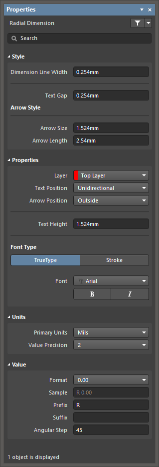
During placement, the panel can be accessed by pressing the Tab key.
To access the properties of a placed Radial Dimension:
- Double-click on the Radial Dimension.
- Right-click on the Radial Dimension then select Properties from the context menu.
- If the Properties panel is already active, click once on the Radial Dimension to select it.
Editing via the PCB List Panel
Panel page: PCB List, PCB Filter
The PCB List panel allows you to display design objects from one or more documents in tabular format, enabling quick inspection and modification of object attributes. Used in conjunction with appropriate filtering - by using the PCB Filter panel, or the Find Similar Objects dialog - it enables the display of just those objects falling under the scope of the active filter – allowing you to target and edit multiple design objects with greater accuracy and efficiency.
Tips
- When the reference arc or circle to which a radial dimension object is attached is deleted, a dialog will open asking whether the dimension should also be deleted. If the dimension is not deleted, it remains in the workspace but non-referenced.
- Dimensions are group objects consisting of text and track segments. They can be converted to their set of primitive objects by choosing Tools » Convert » Explode Dimension to Free Primitives from the main menus. Once exploded, a dimension object can no longer be manipulated as a group object.