
Working with a Region Object on a PCB in Altium Designer
Parent page: PCB Objects
 Examples of the various types of placed region objects
Summary
A Region, also known as a Solid Region, is a polygonal-shaped primitive object that can be placed on any layer.
A region can have any number of sides and vertices (corners). It can be placed on a signal layer to define an area of solid copper to be used to provide shielding or to carry large currents. Positive regions can be combined with tracks or arc segments and be connected to a net. In the PCB Library editor, regions can be used to create custom pad shapes on copper layers or special mask shapes on the solder and paste masks. On non-electrical layers, regions can be used to define custom shapes for tasks such as logos.
When placed as a negative, a region can create a cutout (a void) in a polygon pour. In this mode, the region will not be filled with copper when the polygon is poured. When used as a negative region for a board cutout (by placing it on the multi-layer), it defines an area that becomes a hole through the finished board. Board cutout regions are transferred to Gerber and ODB++ files for manufacturing purposes through the use of a dedicated Rout layer.
Availability
Regions are available for placement in both the PCB editor and the PCB Library editors in one of the following ways:
- PCB Editor:
- Choose Place » Solid Region from the main menus.
- Click the Solid Region button (
 ) in the drop-down on the Active Bar located at the top of the workspace. (Click and hold an Active Bar button to access other related commands. Once a command has been used, it will become the topmost item on that section of the Active Bar.)
 - Right-click in the workspace then click Place » Solid Region from the context menu.
- PCB Library Editor:
- Choose Place » Solid Region from the main menus.
- Click the Solid Region button () in the drop-down on the Active Bar located at the top of the workspace. (Click and hold an Active Bar button to access other related commands. Once a command has been used, it will become the topmost item on that section of the Active Bar.)
Placement
After launching the command, the cursor will change to a crosshair and you will enter region placement mode. Placement is made by performing the following sequence of actions:
- Position the cursor then click to anchor the starting vertex for the region.
- Move the cursor ready to place the second vertex. The default behavior is to place two edges with each click, with a user-defined corner shape between them. Refer to the Placement Modes topic below for more details on changing corner modes.
- Continue to move the mouse and click to place further vertices.
- After placing the final vertex, right-click or press Esc to close and complete placement of the region. There is no need to manually close the region as the software will automatically complete the shape by connecting the start point to the final point placed.
- Continue placing further regions or right-click or press Esc to exit placement mode.
Additional actions that can be performed during placement include:
- Press the Tab key to pause the placement and access the Region mode of the Properties panel from where its properties can be changed on-the-fly. Click the workspace pause button overlay (
 ) to resume placement.
 - Press the + and - keys on the numeric keypad to cycle forward and backward through all layers currently visible in the design.
- Press the * key to cycle through the visible signal layers.
Graphical Editing
Move Region Vertices
Regions contain two points, or "handles", with which to edit the shape of the region.
- Full Handles - located at the corners of the region.
- Empty Handles - located in the centers of the segments created by the Full Handles.
An existing region can be re-shaped by moving these handles, or vertices, located at each corner or at the center of each edge.
To modify the region shape:
- Click and select a region, which will highlight the vertices for the region and change the cursor to a crosshair.
- Click on a Full Handle to move that corner.
- Click along an edge to move the entire edge.
- Click on an Empty Handle to move the whole side (for track and for arc).
- Ctrl+Click on an Empty Handle to break that edge into two edges. Ctrl only needs to be held at the beginning of movement. The Shift+Spacebar hotkeys can then be used to cycle through modes (arc, miter, and any angle).
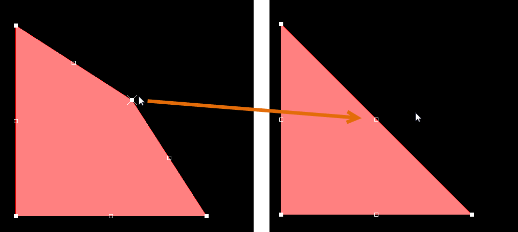
 The various methods of moving region vertices.
- If the any angle placement mode creates unwanted vertices, or to remove extra vertices in general, click Ctrl and grab the central full handle. An X icon appears over the handle and dragging the edge will reduce the vertices on that edge to one.
Modify Region Border
In addition to vertex editing, you also can use the Modify Region Border command to easily change the shape of polygons. The command is run by right-clicking on the desired polygon then selecting Polygon Actions » Modify Polygon Border. Once the command is launched, the cursor becomes a crosshair. Each time you click, a new vertex is added. As during region placement, the Shift+Spacebar shortcuts can be used to change corner shapes.
 Modifying a region border.
Non-Graphical Editing
The following methods of non-graphical editing are available:
Via the Properties Panel
Properties page: Region Properties
This method of editing uses the associated Properties panel mode to modify the properties of a Region object.

The Region mode of the Properties panel
During placement, the Region mode of the Properties panel can be accessed by pressing the Tab key.
After placement, the Region mode of the Properties panel can be accessed in one of the following ways:
- Double-click on the placed Region object.
- Place the cursor over the Region, right-click then choose Properties from the context menu.
- If the Properties panel is already active, select the Region object.
Editing via a List Panel
Panel pages: PCB List, PCBLIB List
A List panel allows you to display design objects from one or more documents in tabular format, enabling quick inspection and modification of object attributes. Used in conjunction with appropriate filtering, it enables the display of just those objects falling under the scope of the active filter – allowing you to target and edit multiple design objects with greater accuracy and efficiency.