
Configuring PCB Polygon Pour Object Properties in Altium Designer
Parent page: Polygon Pour
PCB Editor object properties are definable options that specify the visual style, content and behavior of the placed object. The property settings for each type of object are defined in two different ways:
- Pre-placement settings – most Polygon Pour object properties, or those that can logically be pre-defined, are available as editable default settings on the PCB Editor - Defaults page of the Preferences dialog (accessed from the
 button at the top-right of the workspace). Select the object in the Primitive List to reveal its options on the right.
 - Post-placement settings – all Polygon Pour object properties are available for editing in the Properties panel when a placed Polygon Pour is selected in the workspace.

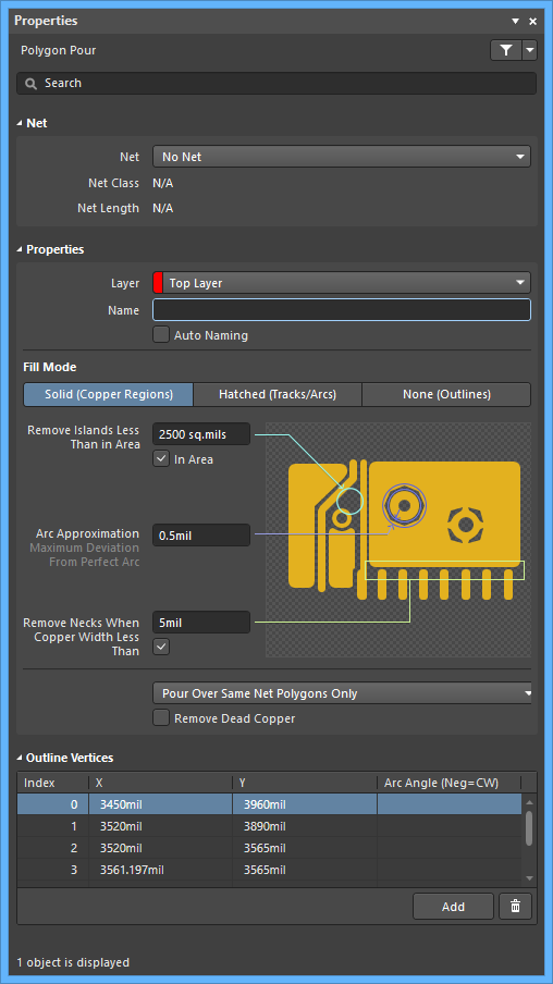 The Polygon default settings in the Preferences dialog and the Polygon Pour mode of the Properties panel
Net (Properties panel only)
- Net - use the drop-down to select the net to which this polygon belongs. All nets for the active board design will be listed in the drop-down list. Note that if polygon placement commences at the same location as an existing object that is already connected to a Net, then the Net property of the new object is automatically assigned to that Net.
- Net Class - displays the net class. Ths field is dependent upon the net selected in the Net field and is not editable.
- Net Length - displays the net length. Ths field is dependent upon the net selected in the Net field and is not editable.
Properties
- Layer - use the drop-down to select the layer on which the polygon is placed.
- Name - specify a suitable name for the polygon. As well as helping identify each polygon, the name can be used to target a specific polygon (or family of polygons) in a design rule.
- Auto Naming - enable this option to have automatic polygon naming applied to the polygon. Naming is based on the chosen naming scheme specified in the Polygon Naming Scheme field of the Board mode of the Properties panel.
- Fill Mode - choose the fill mode for the polygon pour. There are three modes available, each with their own advantages and options:
-
Solid (Copper Regions) - region-based polygons result in far fewer objects being placed making for: smaller files, faster redraws, file opening, and DRC and net connectivity analysis, and smaller output files as the region object is fully supported in Gerber and ODB++. The preview image changes to present a graphical depiction of a solid polygon pour with the following associated options:
- Remove Islands Less Than In Area - specify an area value. Any islands of polygons whose area is smaller than this value will be removed.
- Arc Approximation - specify the maximum deviation from a perfect arc (curved edges are created from multiple short, straight edges).
- Remove Necks When Copper Width Less Than - specify a width value. Polygon pour copper with width is smaller than this value will be removed. Typically this is set to be no smaller than the smallest width track used in the design, or the smallest copper width supported by the fabricator.
- Hatched (Tracks/Arcs) - track/arc based polygons allow a hatched polygon to be created by setting the Track Width to be smaller than the Grid Size. Note that they can also be solid by setting the Track Width to be larger than the Grid Size. The preview image changes to present a graphical depiction of a hatched polygon pour with the following associated options:
- Grid Size - specify the spacing, or grid, that the tracks are placed on for the hatched polygon.
- Track Width - specify the width of track used to create the polygon.
- Surround Pads With - specify the shape used to surround the pads: Arcs or Octagons.
- Hatch Mode - there are four modes available: 90 Degree, 45 Degree, Horizontal, or Vertical.
- Min Prim Length - specify how short the track/arc objects in the fill mode are allowed to be.
- Pour Over Same Net Polygons Only - use the drop-down to select which other kinds of objects in the same net to also pour over:
- Don't Pour Over Same Net Objects - select this option for the polygon to pour around all other objects regardless of the net to which they belong.
- Pour Over All Same Net Objects - select this option for the polygon to pour over all objects on the same net as the polygon that are within the polygon's area. For example, existing routes on that net will be completely covered by the polygon.
- Pour Over Same Net Polygons Only - select this option for the polygon to only pour over existing polygon objects on the same net as this polygon. The polygon will pour around all other objects regardless of the net to which they belong.
- Remove Dead Copper - enable this option to remove any isolated area of polygon copper that does not connect to the specified net. Note that a polygon that is not connected to a net is considered to be Dead Copper and it will be completely removed if this option is enabled.
- None (Outlines) - outlines only polygons are simply track/arc polygons without the internal tracks and arcs. The preview image changes to present a graphical depiction of an outline only polygon pour, with the following associated options:
- Grid Size - not available for this fill mode.
- Track Width - specify the track width for polygon outline.
- Surround Pads With - specify the shapes to surround the pads: Arcs or Octagons.
- Hatch Mode - this option is not available for this fill mode.
- Min Prim Length - specify how short the track/arc objects in the fill mode are allowed to be.
- Pour Over Same Net Polygons Only - use the drop-down to select which other kinds of objects in the same net to also pour over:
- Don't Pour Over Same Net Objects - select this option for the polygon to pour around all other objects regardless of the net to which they belong.
- Pour Over All Same Net Objects - select this option for the polygon to pour over all objects on the same net as the polygon that are within the polygon's area. For example, existing routes on that net will be completely covered by the polygon.
- Pour Over Same Net Polygons Only - select this option for the polygon to only pour over existing polygon objects on the same net as this polygon. The polygon will pour around all other objects regardless of the net to which they belong.
- Remove Dead Copper - enable this option to remove any isolated area of polygon copper that does not connect to the specified net. Note that a polygon that is not connected to a net is considered to be Dead Copper and it will be completely removed if this option is enabled.
-
Outline Vertices (Properties panel only)
Use this region to modify the individual vertices of the currently selected polygon pour object. You can modify the locations of existing vertices, add new vertices or remove them as required. Arc connections between vertex points can be defined and you can also adjust the position of the polygon pour object by globally applying delta-x/delta-y values to all vertex points.
- Vertices Grid - lists all the vertex points currently defined for the polygon pour.
- Index - the assigned index of the vertex (non-editable).
- X - the X (horizontal) coordinate for the vertex. Click to edit.
- Y - the Y (vertical) coordinate for the vertex. Click to edit.
- Arc Angle (Neg=CW) - the angle of an arc that is drawn to connect this vertex point to the next. By default, connections are straight line edges with this field remaining blank. Click to edit then enter an arc angle as required. Entry of a positive value will result in an arc drawn counterclockwise. To draw a clockwise arc, enter a negative value.
- Add - use to add a new vertex point. The new vertex will be added below the currently selected (highlighted) vertex entry and will initially have the same coordinates as the previously selected entry.
-
 - click to delete the currently selected vertex entry. You will be prompted for confirmation before the deletion occurs.