
Configuring PCB Radial Dimension Object Properties in Altium Designer
Created: 3月 03, 2021 | Updated: 4月 09, 2021
| Applies to version: 21
This document is no longer available beyond version 21. Information can now be found here: Properties of Dimension Objects for version 24
Parent page: Radial Dimension
PCB Editor object properties are definable options that specify the visual style, content and behavior of the placed object. The property settings for each type of object are defined in two different ways:
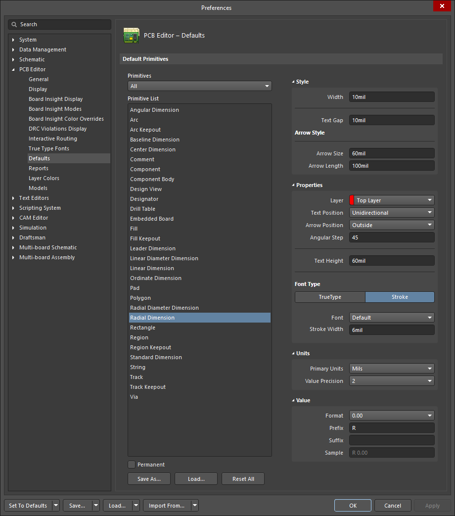
- Pre-placement settings – most Radial Dimension object properties, or those that can logically be pre-defined, are available as editable default settings on the PCB Editor - Defaults page
of the Preferences dialog (accessed from the
 button at
the top-right of the design space). Select the object in the Primitive List to reveal its options on the right.
button at
the top-right of the design space). Select the object in the Primitive List to reveal its options on the right.
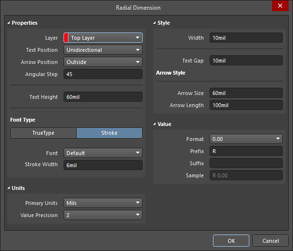
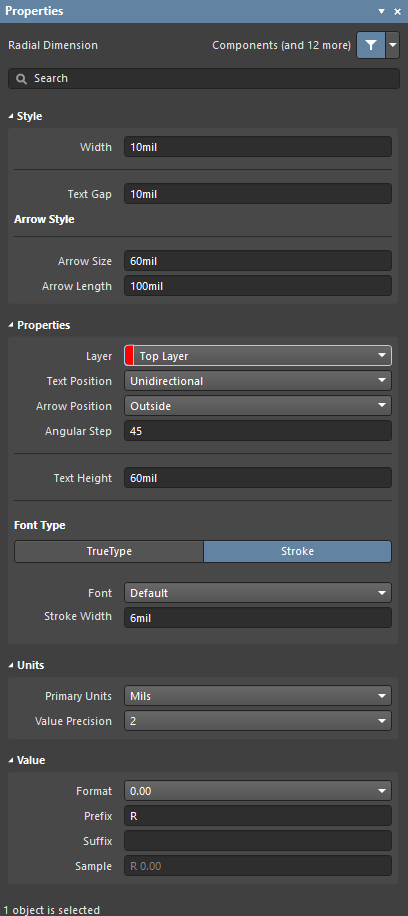
- Post-placement settings – all Radial Dimension object properties are available for editing in the Radial Dimension dialog and the Properties panel when a placed Radial Dimension is selected in the design space.
Style
- Width - the current dimension line width.
- Text Gap - the current gap to the left and right of the dimension value text.
Arrow Style
- Arrow Size - the current arrowhead size. The size is measured as the distance between the arrow tip and the end of the arrow 'legs'.
- Arrow Length - the current arrow length. Note that the value entered into this field is applied only when the Arrow Position (in the Properties region) is set to Outside.
Properties
- Layer - the layer to which the dimension is currently assigned. Dimensions can be assigned to any available layer. Use the drop-down to select a different layer.
- Text Position - the current position of the dimension text. Use the associated drop-down list to choose one of the following options:
- Aligned - Left - the dimension text will be aligned with the angle of the dimension line.
- Unidirectional - the dimension text will remain horizontal regardless of the dimension alignment angle.
- Manual - the dimension text will be available for manual placement.
- Arrow Position - the current position of the dimension arrows. The available options are:
- Inside - arrows will be positioned inside the dimension's extension lines (pointing outwards).
- Outside - arrows will be positioned outside the dimension's extension lines (pointing inwards).
- Text Height - the current height of the dimension text characters. The character width used to display or print the text is automatically proportioned to this height. A minimum height of 36mil (0.9mm) will allow the text to be legibly photo-plotted.
Font Type
- TrueType - use this field to choose the required TrueType font. The drop-down list is populated with TrueType and OpenType (a superset of TrueType) fonts found in the \Windows\Fonts folder. Note that the list will only include entries for detected (and uniquely named) root fonts. Use the B (bold) and I (italic) options to add emphasis to the text.
- Stroke
- Font - use this field to choose the required Stroke font. Available options are:
- Default - a simple vector font that supports pen plotting and vector photo-plotting.
- Serif - a more complex font that will slow down vector output generation, such as Gerber.
- Sans Serif - a more complex font that will slow down vector output generation, such as Gerber.
- Font - use this field to choose the required Stroke font. Available options are:
-
Stroke Width - displays the current stroke width.
Units
- Primary Units - the current unit that is selected for the calculation and display of the dimension value.
- Value Precision - the current setting for the number of decimal places to the right of the decimal point for which the dimension will be displayed.
Value
- Format - the current setting for the format of the dimension text. Use the associated drop-down to change the format as required. The options listed will depend on the chosen Unit and present based
on the actual value for the current dimension. In generic terms, the available options are:
- None - no dimension text is displayed.
- Value Only - no units are displayed, only the dimension value (e.g., 600.00).
- Value and Unit - units are displayed after the dimension value (e.g., 600.00mil).
- Value and Bracketed Unit - units are displayed in brackets after the dimension value (e.g., 600.00(mil)).
- Prefix - the current prefix to the dimension value.
- Suffix - the current suffix to the dimension value.
- Sample - this field presents a sample of how the dimension text will appear in accordance with specified Format and any defined Prefix and/or Suffix.