
Working with a Signal Harness Object on a Schematic Sheet in Altium Designer
This document is no longer available beyond version 21. Information can now be found here: Signal Harness for version 24
Parent page: Schematic Objects
 A placed Signal Harness
Summary
A Signal Harness is an electrical design primitive. It is an abstract connection that enables the logical grouping of different signals including buses, wires and other signal harnesses for increased flexibility and streamlined design. Signal Harnesses allow for the creation and manipulation of higher level abstract connections between sub-circuits in your PCB Projects. They allow for a more complex design within the same schematic design space, which increases the readability of designs and builds potential for reuse.
Availability
Signal harnesses are available for placement in the Schematic Editor in one of the following ways:
- Choose Place » Harness » Signal Harness from the main menus.
- Click the Signal Harness button (
 ) in the graphic objects drop-down on the Active Bar located at the top of the design space. (Click and hold an Active Bar button to access other related commands. Once a command has been used, it will become the top-most item on that section of the Active Bar.)
 - Right-click in the design space then choose Place » Harness » Signal Harness from the context menu.
- Click the button on the Wiring toolbar.
Placement
After launching the command, the cursor will change to a cross-hair and you will enter signal harness placement mode. Placement is made by performing the following sequence of actions:
- Click or press Enter to anchor the starting point for the signal harness.
- Position the cursor then click or press Enter to anchor a series of vertex points that define the shape of the signal harness.
- After placing the final vertex point, right-click or press Esc to complete placement of the signal harness.
- Continue placing further signal harness objects or right-click or press Esc to exit placement mode.
- Use the Backspace or Delete keys to remove the last harness segment placed.
Additional actions that can be performed during placement while the signal harness is still floating on the cursor and before its first corner is anchored are:
- Press the Tab key to pause the placement and access the Signal Harness mode of the Properties panel from where its properties can be changed on the fly. Click the design space pause button overlay (
 ) to resume placement.
Placement Modes
When placing a signal harness there are three 'manual' placement modes, two of which have Start and End sub-modes. The mode specifies how corners are created when placing signal harnesses and the angles at which signal harnesses can be placed. During placement:
- Press Shift+Spacebar to cycle through the modes.
- While in the 90 Degree or 45 Degree mode (known as true orthogonal modes), press Spacebar to cycle between the Start and End sub-modes.
- During placement, the current placement mode is displayed in the Status bar. You can change modes at any time during signal harness placement.
- In modes other than Any Angle, the line segment attached to the cursor is a look-ahead segment. The segment you are actually placing precedes this look-ahead segment.
 45 degree mode
 90 degree mode
 Any angle mode Press Shift+Spacebar to cycle through the different placement modes.
Guided Wiring of a Signal Harness
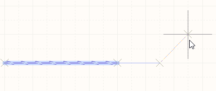
Schematics have a definable electrical grid that makes it easy to define electrical connections between objects. While placing a Signal Harness, when the Signal Harness falls within the electrical grid range of another electrical object, the cursor will snap to the fixed object and a Hot Spot (blue cross) will appear.
") Hot Spot (blue cross)
Hot Spot (blue cross)
The Hot Spot guides you to where a valid connection can be made and automatically snaps the cursor to electrical connection points.
The electrical grid can be defined in the General region of the Properties panel in Document Options mode (accessed when no objects are selected in the design space). It is recommended that you set the electrical grid to be slightly smaller than the current snap grid, or it becomes difficult to position electrical objects one snap grid apart.
Graphical Editing
This method of editing allows you to select a placed signal harness object directly in the design space and change its size and/or shape graphically.
When a signal harness object is selected, the following editing handles are available:
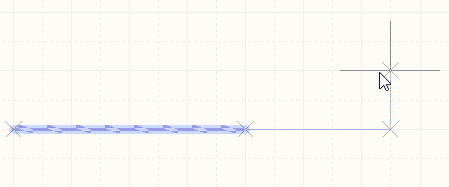
 A selected Signal Harness, ready for graphical editing
- Click and drag A to reposition the end points of the signal harness.
- Click and drag B to move a signal harness vertex. The end points will remain anchored.
- Click and drag on a segment to grab that segment and reposition it. The end points and other vertices will remain anchored.
- Right-click on a vertex point then choose the Edit Signal Harness Vertex n command to edit.
- Click and hold on a vertex, then press Delete on the keyboard to remove that vertex.
With the signal harness selected, click on a segment to individually select that segment. This harness 'sub-selection' is distinguished by the associated editing handles becoming red in color.
 Individual segment sub-selection
The associated vertices for the segment can then be edited directly using the SCH List panel and any changes will appear immediately on the schematic.
Non-Graphical Editing
The following methods of non-graphical editing are available.
Editing via the Signal Harness Dialog or Properties Panel
Properties page: Signal Harness Properties
This method of editing uses the associated Signal Harness dialog and the Properties panel mode to modify the properties of a signal harness object.
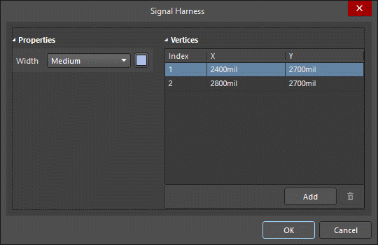
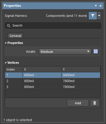 The Signal Harness dialog, on the left, and the Signal Harness mode of the Properties panel on the right
After placement, the Signal Harness dialog can be accessed by:
- Double-clicking on the placed signal harness object.
- Placing the cursor over the signal harness object, right-click, then choose Properties from the context menu.
During placement, the Signal Harness mode of the Properties panel can be accessed by pressing the Tab key. Once the signal harness is placed, all options appear.
After placement, the Signal Harness mode of the Properties panel can be accessed in one of the following ways:
- If the Properties panel is already active, by selecting the signal harness object.
- After selecting the signal harness, select the Properties panel from the Panels button at the bottom right of the design space or select View » Panels » Properties from the main menu.
Editing Multiple Objects
The Properties panel supports multiple object editing, where the property settings that are identical in all currently selected objects may be modified. When multiples of the same object type are selected manually, via the Find Similar Objects dialog or through a SCH Filter or SCH List panel, a Properties panel field entry that is not shown as an asterisk (*) may be edited for all selected objects.
Editing via a List Panel
Panel pages: SCH List, SCH Filter
A List panel allows you to display design objects from one or more documents in tabular format, enabling quick inspection and modification of object attributes. Used in conjunction with appropriate filtering - by using the SCH Filter panel, or the Find Similar Objects dialog - it enables the display of just those objects falling under the scope of the active filter – allowing you to target and edit multiple design objects with greater accuracy and efficiency.
Autojunctions
A T-junction in a signal harness is automatically connected by a junction (Compiler-Generated Junction). If the Break Wires At Autojunctions option is enabled on the Schematic - General page of the Preferences dialog, an existing signal harness segment will be broken into two at the point where an autojunction is inserted. For example, when making a T-Junction, the perpendicular signal harness segment will be broken into two segments, one on each side of the junction. With this option disabled, the signal harness segment will remain unbroken at the junction.
Working with Signal Harnesses
The term Signal Harness is used to describe both the bus-like line that runs between a Harness Connector and a Harness Port and also the overall connectivity system created by these connected harness objects.
 The term Signal Harness is used to describe the bus-like line that runs between a Harness Connector and a Port, and also the harness connection system.
To learn more, refer to Working with Signal Harnesses.