
Configuring Draftsman Counter Hole View Object Properties in Altium NEXUS
Parent page: Counter Hole View
Draftsman object properties are definable options that specify the visual style, content and behavior of the placed object. The property settings for each type of object are defined in two different ways:
-
Pre-placement settings – most Counter Hole View object properties, or those that can logically be pre-defined, are available as editable default settings on the Draftsman - Defaults page of the Preferences dialog (access from the
 button at the top-right of the design space). Select the object in the Primitive List to reveal its options on the right.
 -
Post-placement settings – all Counter Hole View object properties are available for editing in the Properties panel when a placed Counter Hole View is selected in the design space.

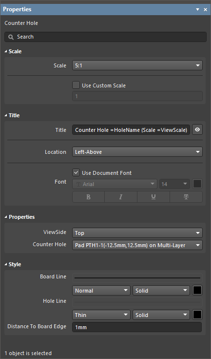
The Counter Hole View default settings in the Preferences dialog and the Counter Hole mode of the Properties panel
Scale
- Scale – use the drop-down to choose from a range of preset scale ratios (magnification). This option is not available if the Use Custom Scale option is checked.
- Use Custom Scale – select this option to enter a specific scale in its associated field. The scaling of the drawing object is relative to
1, where0.9would represent a scale of 90%.
Title
- Title – the title name string that will be displayed (if enabled) with the Counter Hole View object. Use the associated
 button to toggle its visibility. Enter the title name and any desired system/custom parameters to create a meaningful name for the placed view. See the Parameters section in the Properties panel's Document Options mode for a list of the currently available parameters.
 - Location – use the drop-down to choose from a range of relative locations for the title. The Manual option is automatically selected if the title is manually moved (dragged and dropped to a new location).
- Font – sets the displayed font used for the view's title string.
- Use Document Font checkbox selected – the title font used is that defined by the document options. See the Document Font entry in the General section of the Properties panel when in Document Options mode.
- Use Document Font not selected – use the drop-down menus to choose the desired font type and size and select the lower buttons to enable text attributes. The associated color button (
 ) opens the color selector where the font color can be specified by RGB or HEX value, by freeform selection, or from a range of presets. Note that the slider control sets the color Opacity level where 0% represents full transparency.
Properties
- ViewSide – the direction of view used to render the hole drawing. Use the drop-down menu to select from a range of preset view directions.
- Counter Hole (Properties panel only) – the board design pad with a counter hole feature applied which hole will be rendered in the Counter Hole View. Use the drop-down menu to select from the list of all available counter holes.
Style
- Board Line – the thickness and style of the board line. Use the drop-down menus to choose from a range of line thickness presets and the line style. The associated color button () opens the line color selector dialog as outlined for Font above.
- Hole Line – the line thickness and style used to render the hole geometry in the Counter Hole View. Use the drop-down menus to choose from a range of line thickness presets and the line style. The associated color button () opens the line color selector dialog as outlined above.
- Distance To Board Edge – specifies the distance from the counter hole view to the edge of the board (for the
LeftViewSide of the Counter Hole View).