
Restructuring a Design through Refactoring in Altium NEXUS
Parent page: More about Schematics
Refactoring, in the traditional sense, is the act of restructuring an existing design (or body of code in programming land) without changing the functionality of that design (or code). In terms of PCB design, there are various situations in which some form of refactoring would provide a beneficial and timely solution:
- A part has become obsolete and needs to be replaced by a functionally-equivalent sub-circuit. (Show Me)
- A schematic design is to become a sub-circuit for use within a larger design. (Show Me)
- An existing schematic sub-sheet is to be made into a device sheet for reuse across future designs. (Show Me)
- An existing device sheet needs to be localized and customized for the current design. (Show Me)
- Some existing sub-circuitry needs to be moved to another sheet. (Show Me)
Altium NEXUS provides a number of features that collectively form its Design Refactoring capabilities - giving you maximum flexibility to restructure your designs according to requirements.
Converting a Part to a Sheet Symbol
This feature is ideal where an existing part has become obsolete and needs to be replaced by a functionally-equivalent sub-circuit, defined on a separate sheet.
Right-clicking on a part and choosing the Part Actions » Convert Part To Sheet Symbol command from the context menu, converts the part symbol into a sheet symbol. Connectivity is retained, with the sheet entries named as per the original pin naming, and I/O Type set to reflect the original pin electrical type.
The sheet symbol's Designator is initially set to the original part's designator, and its File Name initially set to the part's comment text.
 Convert an existing part into a sheet symbol.
If the required child sheet exists, change the sheet symbol's File Name to point to that sheet. If not, a sub-sheet can quickly be created by right-clicking on the sheet symbol and choosing the Sheet Symbol Actions » Create Sheet From Sheet Symbol command. In this latter case, ports corresponding to the symbol's sheet entries will be placed on the new sub-sheet, ready for the replacement sub-circuitry to be defined and hooked up.
Pushing a Part onto a New Sub-Sheet
An alternative, and perhaps faster method to achieve a similar end result, is to right-click on the required part and choose the Part Actions » Push Part To Sheet command. The following sequence of steps are essentially performed:
- The part is copied.
- The original part is converted to a sheet symbol with Designator set to the designator of the original part, and File Name set to <OriginalPartComment>.SchDoc. Again, sheet entry naming and I/O Type reflect the pins of the original part.
- A new schematic sheet is created from the sheet symbol, named using the symbol's File Name value.
- The copy of the original part is pasted at the center of the sheet, with ports corresponding to the sheet symbol's sheet entries placed and wired to the part's pins.
You can then delete the part and replace it with functionally-equivalent circuitry, as required.
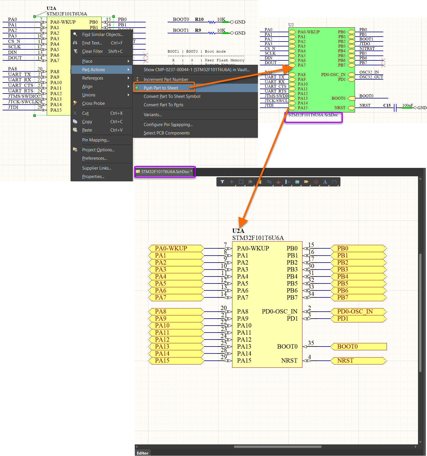 Using the Push Part To Sheet command quickly converts the initial part into a sheet symbol, then pastes a copy of that part on a newly created sheet,
referenced by that symbol.
Converting a Part to Ports
This feature is ideal for when an existing standalone sub-design, such as a power supply or a satellite board, is to be made into a sub-circuit, to be used within a larger, single board design - perhaps to minimize manufacturing costs. This is the reverse of the previous section, which was replacing a component with a lower-level sub-circuit. Rather this is the process of plugging a sub-circuit into the higher-level design, making it available for connection to a point above in the hierarchy.
Right-clicking on a part and choosing the Part Actions » Convert Part To Ports command from the context menu, converts the part symbol into a set of ports. Connectivity is retained, with the ports named as per the original pin naming, and I/O Type set to reflect the original pin electrical type.
 Use the Convert Part To Ports command to quickly replace a part with ports by which to hook a sub-circuit into a higher-level design.
The sub-circuit's insertion into the hierarchy is then completed by adding a sheet symbol on the relevant higher-level parent sheet. To do this:
- Make the required parent sheet active.
- Use the Design » Create Sheet Symbol From Sheet command.
- Choose the document (containing the ports created from the part) in the Choose Document to Place dialog.
- A sheet symbol will appear on the cursor - position within the sheet as required, and click to effect placement.
The sheet symbol references the underlying sub-sheet (through its File Name property) and has sheet entries corresponding to the ports on the child sheet.

Use the Create Sheet Symbol From Sheet command to quickly add a sheet symbol, thereby threading the sub-circuit into the design hierarchy.
Converting a Schematic Sheet to a Device Sheet
At some stage, the concept of designing for reuse has to increase in its abstraction. If we stopped at the component level, then each design that featured a similar piece of functionality - such as a USB interface, or voltage regulator - would be ‘reinventing the wheel’ as it were. And that’s where Device Sheets come into play - schematic sheets designed to offer specific circuit functionality. Their use removes the risks associated with the traditional copy-and-paste approach. And they eliminate the repetition of design effort while adding to the level of design content that can be reused in future designs.
As part of its Refactoring tool suite, the Schematic Editor provides the ability to quickly convert an existing standard schematic sheet into a device sheet, for reuse in other designs.
To convert an existing schematic sheet into a device sheet:
- Locate the sheet symbol - referencing the required sheet - on the relevant parent page in the design hierarchy.
- Select the sheet symbol and choose the Edit » Refactor » Convert Selected Schematic Sheet To Device Sheet command from the main menus. The Convert Schematic Sheet to Device Sheet dialog will appear. Choose the target location in which to store the newly-created device sheet, and also the scope of the conversion - whether to update the current sheet symbol, or all relevant sheet symbols in the workspace or active project. The latter is particularly useful for a multi-channel design, where the sub-circuit exists in several instances.
 Specify details of the conversion in the Convert Schematic Sheet to Device Sheet dialog.
 button to the right of the location field to access the
 - Click OK. The sheet symbol will be converted to a device sheet symbol, and the schematic will be moved to the nominated device sheet location.
- Recompile the project to have the new device sheet appear in the Projects panel.
 Recompile the project to have the device sheet appear correctly in the design hierarchy.
Converting a Device Sheet to a Schematic Sheet
Device sheets enable functional sub-circuits to be captured and reused across designs. However, there may be a need to modify an existing sub-circuit for a particular design. Rather than modifying the device sheet itself, the Schematic Editor provides the ability to take a copy of the device sheet, making its circuitry available on a standard schematic sheet. This allows you to modify the local copy in-line with requirements for your current design, and safe in the knowledge that the original device sheet remains untouched.
To 'convert' an existing device sheet into a schematic sheet:
- Locate the device sheet symbol that references the required device sheet.
- Select the device sheet symbol and choose the Edit » Refactor » Convert Device Sheet To Schematic Sheet command from the main menus. The Convert Device Sheet to Schematic Sheet dialog will appear. Choose the target location in which to store the newly-created schematic sheet, and also the scope of the conversion - whether to update the current device sheet symbol, or all relevant device sheet symbols in the active project.
 Specify details of the conversion in the Convert Device Sheet to Schematic Sheet dialog.
- Click OK. The device sheet symbol will be converted to a sheet symbol, and a copy of the device sheet will be stored locally as a standard (unprotected) sheet in the nominated location. The sheet symbol will reference this local sheet.
 The local schematic sheet will replace the previous device sheet, in the Projects panel, after the conversion.
Moving Selected Sub-Circuitry to a Different Sheet
As a design evolves, the content of the source schematic sheets that comprise that design may need to be shifted around - a specific portion of circuitry may 'read' better on its own sheet, or perhaps a sheet is becoming overloaded (and unreadable!) and could benefit from moving some circuitry to an additional/different sheet.
Another refactoring feature is the ability to select one or more objects on a sheet, and move that selection to a different sheet. To do this:
- First select the circuitry that you want to move.
- Right-click and choose the Edit » Refactor » Move Selected Subcircuit to Different Sheet command from the context menu. The Choose Destination Document dialog will appear - use this to nominate the target schematic sheet.
 Relocate part of a design to a different schematic sheet.
- Click OK. The chosen sheet will be made active and the selected sub-circuit will appear floating on the cursor.
- Position the circuitry on the sheet as required, and click to effect placement. Once placed, that circuitry will be removed from the original sheet.
- If moving to a new sheet, add a sheet symbol to the relevant parent page to slot that sheet correctly into the design hierarchy.
- Recompile the design project.