Draftsman provides an advanced, yet flexible graphical editing environment for creating board design production documents. Based on a dedicated file format and set of drawing tools, the Draftsman drawing system provides an interactive approach to bringing together fabrication and assembly drawings with custom templates, annotations, dimensions, callouts, and notes.
Do I have Draftsman installed?Expand折りたたむ
The Draftsman PCB drawing capabilities are available through an Altium NEXUS Extension application, which is automatically installed with Altium NEXUS. The extension can be manually installed/removed or updated from the Altium NEXUS Extensions and Updates page (select the Extensions and Updates option from the system User menu –  ). The Draftsman extension is located within the Installed tab and within the Updates tab when a software update is available.
► See Extending & Updating Your Installation for more information on installing and managing Altium software Extensions.
Key Features
The Draftsman drawing application can act as an adjunct, or even an alternative, to the production of graphical-type PCB production documents using traditional outputs. It offers automated placement of assembly and fabrication drawings on demand, and includes a wide range of manual drawing tools that can be used to add important details and highlighting to its multi-page documents.

Place drawing views, objects and automated annotations on single or multi-page Draftsman documents.
Draftsman's key features include:
- Automated extraction of drawing data from the source PCB document.
- Creation of multi-page documents.
- The application of separate templates to each page of a document.
- Automatic generation of drawings from customized templates.
- Broad range of drawing views (Assembly View, Fabrication View, Section View, Drill Drawing View, Board Region View, etc.).
- Assembly Views that include graphics generated from 3D Models (without the requirement for special PCB layers).
- A customizable Layer Stack Legend with the option to add detailed layer information.
- A BOM table that integrates with ActiveBOM to show all board items or only those items for a selected Assembly View.
- Placement of Callouts to indicate BOM item positions or items from a Notes list.
- Support of assembly Variants.
- User preference settings for drawing objects and functions (accessed via the system
 button).
- Print and Export to PDF outputs.
- Inclusion in OutJobs, where a Draftsman PCB Drawing file can be added as a new Documentation Output.
- ...and much more.
Documentation Outputs
Draftsman documents may be printed or generated as output files in the same manner as other graphics-based documents in Altium NEXUS (Schematic, PCB, etc.). New Draftsman documents (once saved) are automatically added to the associated PCB project and are, therefore, available to all normal document generation and printing processes.
Print or Export to PDF
To print the currently active drawing document, select File » Print from the main menu (or Ctrl+P) and select the print options in the normal way. For Draftsman documents, the print dialog includes a scalable print preview with page navigation selectors.
To export a drawing document to a single or multi-page PDF file (as determined by the document structure), select File » Export to PDF from the main menu.
DXF Import-Export
A .dxf file can be imported into the currently active drawing document, and the currently active drawing document can be exported in .dxf format.
Learn more: DXF Import, DXF Export
Add to OutJob
A Draftsman drawing document is added to an OutJob by first opening an existing Output Job file or creating a new Output document (File » New » Output Job File).
To add a Draftsman document to the output job, select the Add New Documentation option under the Documentation Outputs section, and then select Draftsman and a PcbDwF file (or all available documents). Assign the newly added Output file (*.PcbDwF) to a PDF output by selecting that container option and then checking the enable option associated with the Draftsman entry.

Variant Parameters and OutJobs
Altium NEXUS has the ability to create variations of a board design (Variants) and pass this variant information on to Draftsman, which in turn allows a design variation to be applied to a placed drawing View.
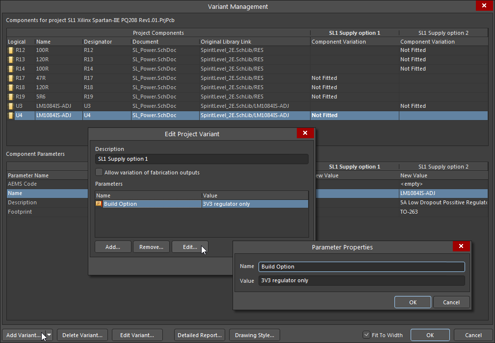
Project Variants are added in the project's Variant Management dialog, which also allows Parameters to be added to each variant. These parameters are typically applied as special (interpreted) strings in Altium NEXUS documents to indicate which Variant is currently enabled.
In Draftsman, a project’s current variant selection is made from the Variation menu in the Properties region of the Properties panel, which causes a placed Board Assembly View to change to reflect the variation, and apply mesh rendering where required – see the General section in the Properties panel Document Options for Variant display settings.
Special strings, such as the VariantName and Variant Parameters can be placed in the drawing as free strings, or for a more universal solution, included in the title block of Draftsman sheet templates – see the Document Parameters dialog for a list of the available parameter strings.

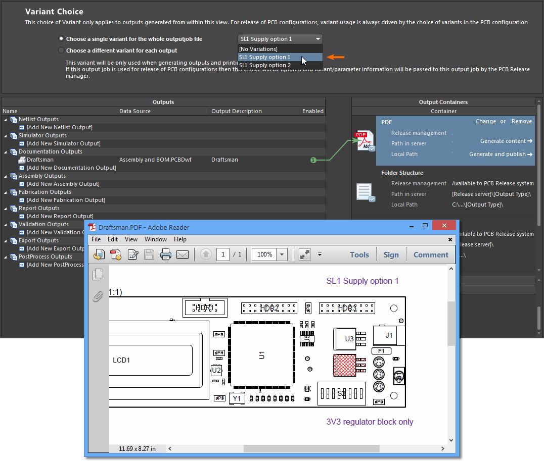
Note that a Draftsman document can have several placed Views, with each potentially set to a different Variant. Since the Variant selection is on an individual View basis, rather than at a document level, any special variant strings placed in the document are not interpreted. When the Draftsman document is printed through an Output Job, the OutJob's current Variant selection (which is at a document level) is resolved by the special strings.
When a saved Draftsman document is subsequently generated from an Altium NEXUS Output Job, the parameter special strings are interpreted in line with the Variant selected in the OutJob. Note that a Variant may be applied to all outputs or specific outputs.