PLM support in the NEXUS Server has been extended and improved with the addition of new PLM configurations, connection validity checks, and configuration structures that directly support the NEXUS Server’s current data model.
► See PLM Integration for more information on working with PLM instances.
Agile support
Along with provision for Windchill® and Arena® PLM instances, support is now included for the Oracle® Agile™ PLM. Base configuration files for Agile PLM support are provided in the downloadable Configuration and Publishing Template sample files.
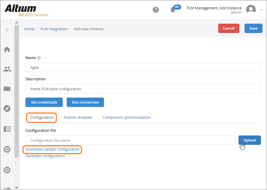
In the server’s Admin – PLM Integration page, select the  button to add a new PLM instance configuration. Use the Download sample configuration link to obtain a local copy of the sample configurations (
ConfigurationSamples.zip) and the  button to browse to and then apply the selected PLM configuration.
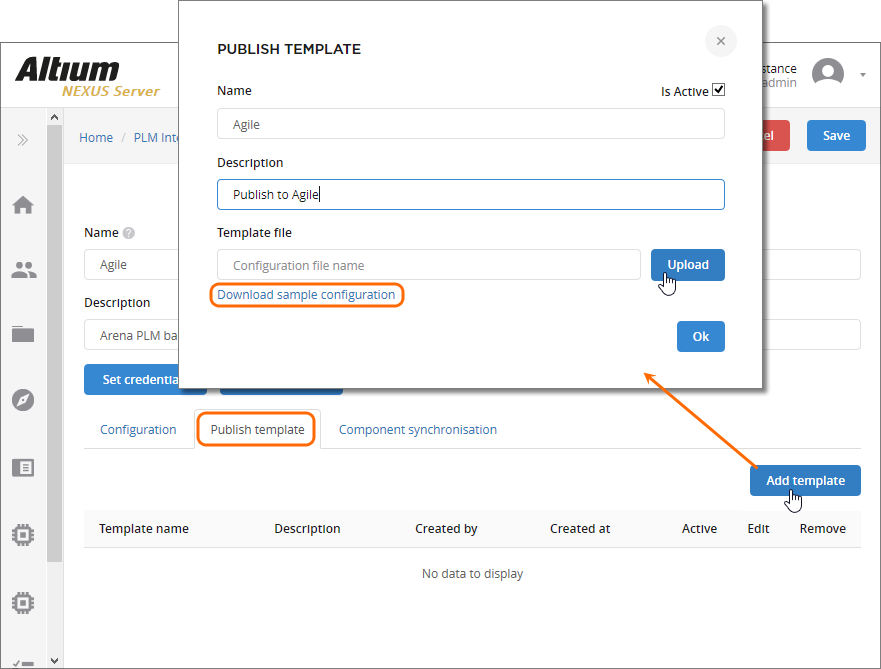
Similarly, a compatible publishing template is added through the  button under the Publish Template tab. In the following Publish Template dialog use the button to browse to and select the correct template file. Use the Download sample configuration link if you have not already obtained the sample templates (
Publish Template Samples.zip).
Select the  button to specify the User name and password for the target PLM instance – click
  to verify access: see below.
The setup files for an Agile PLM instance also supports the Agile Change Order workflow, which is enabled in the Publishing Template file and configured in the Configuration file. When a NEXUS process such as Publish with initialize in PLM is run, the NEXUS process workflow will offer the option of instigating a Change Order workflow in Agile, using an existing Change Order or not using a Change Order at all. Note that subsequent PLM updates to the project will require an Agile Change Order.
Generic driver
PLM Integration in the NEXUS Server now also offers a PLM configuration generator feature that can be used to create a custom configuration for access to, potentially, any PLM instance. The feature is available from the Generate configuration link on the Add new instance page – opened from the button.
In the Generate Configuration dialog select the type of PLM that will be connected to – either one of the already registered types (Windchill etc) or a Custom type – then its remote URL. Select the  button to create a new
 dm-configuration.xml file that may then be saved and added to the new custom PLM instance from the button.
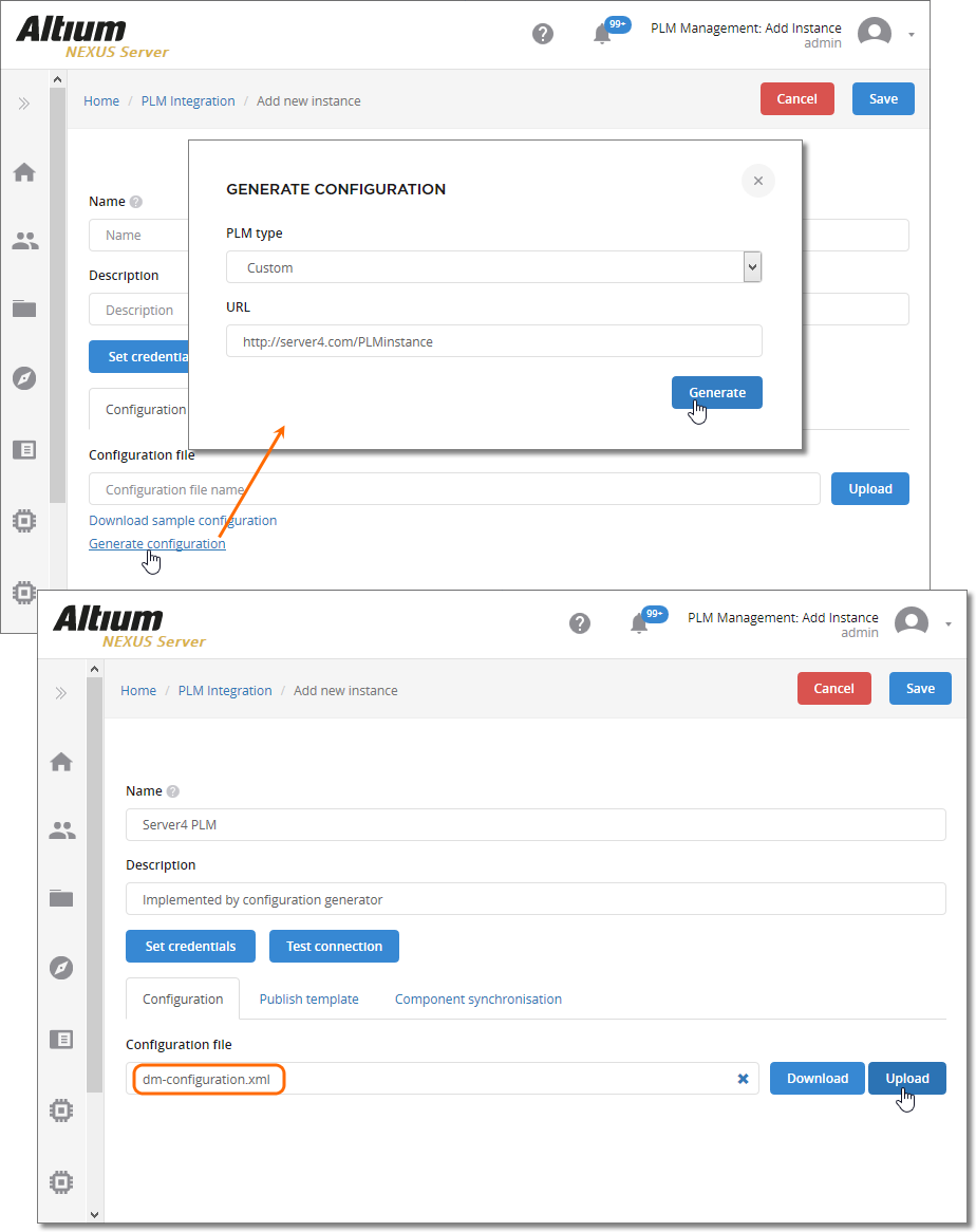
The generator creates the configuration to match the data model of the current NEXUS Server installation, so for example, Component Types that are registered in the server are added as entity types in the configuration file (dm-configuration.xml) – with matching ToPlm and ToAltium sections and mapped parameters. Also included are TODO comments that highlight areas to add or change for compatibility with your Server/PLM configuration. For more information on editing the configuration file to work with your Server/PLM setup, see the explanatory comments included in the supplied sample configuration files.

Enhanced Connection Validation
The PLM Instance connection validation check, available from the button in the Add/Edit Instance page, has been updated to perform a range of configuration compatibility checks and immediately report the results.
When the connection validation report is run, the server analyses the current configuration and publishing template settings for compatibility with both the NEXUS Server and target PLM data. Configuration issues such as path errors, unmatched component type definitions and parameters, invalid Lifecycle or Revision settings are detected and reported in the following Configuration Validation Report dialog.
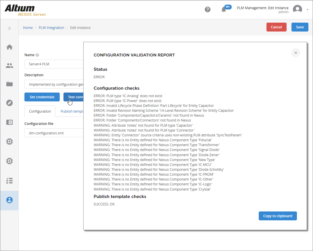
The reported errors and warnings may be then corrected in the applied configuration/publishing files, and/or by making changes in the settings of the server or PLM instance.
PLM Process Report
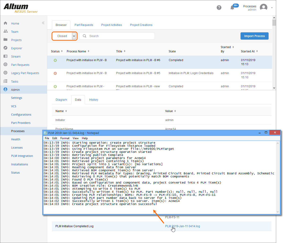
Direct access to a summary report of the steps performed by a workflow process is now available when viewing its completed state. For processes such as Project with initialize in PLM and Publish to PLM, the workflow includes an additional PLM Publish Completed Log Output to generate and return the report file to the user interface.
On the Process Management page (Admin » Processes) select the Browser tab, the Closed processes option and then select the entry of interest. The log file link can be found under the process Data tab.
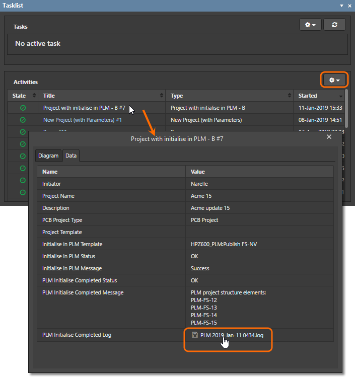
To view the log in the NEXUS design space (client), choose the Show closed option in the Tasklist panel and then select a completed process (task) to open its details dialog. The log file link is available under the dialog’s Data tab.
Synchronization as a Workflow
The ability to synchronize component data between the NEXUS Server and a target PLM instance is now incorporated into a server Process Workflow, which greatly improves the visibility, reporting and error tracing for synchronizing actions. Component (library) synchronization may be performed as a manual or timed process, from the Sync action button (  ) of a PLM instance entry or as an automated cycle specified in the instance setup, respectively.
► See PLM Component Synchronization for more information.
When a NEXUS-PLM synchronization is instigated the LibSync process moves through its predefined Workflow until it completes or encounters an error. Refresh the browser to show the current state of the sync process.
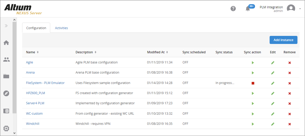
The PLM Management page now includes an Activities tab for monitoring and reviewing LibSync processes, which can be set to show Active (current) or Closed (completed) processes. The LibSync process results are also available in the Process Management page (Admin » Processes) under the Browser tab.
The view’s sub-tabs provide the following information:
- Diagram – a graphic representing the process workflow, with its current step position highlighted (Competed or the error/failure state).
- Data – an information summary of the process action, including the success or failure of its steps and a link to the
![]() logged process report.
logged process report.
- History – a time log of the main Workflow events listed in sequence.
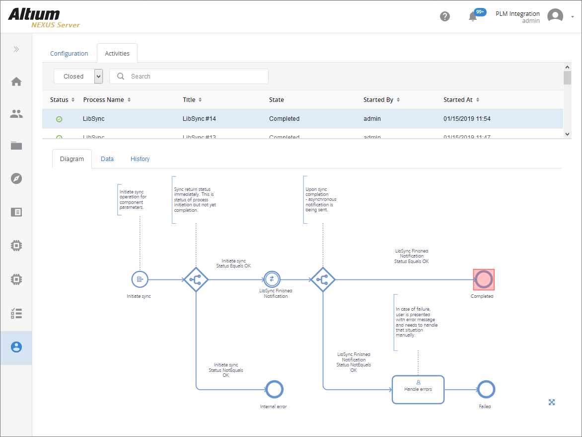
If a LibSync process fails, a Handle errors task is created with associated error data – summary information and process diagram. Current action tasks are available in the Tasks Management page, accessed from the Tasks option on the main menu.
New CSV Uploader
A new CSV Component database importer tool is now included in the NEXUS Server installation. Implemented as a configurable batch (*.bat) file, the desktop tool imports component data from a target spreadsheet file (*.csv) into the server as determined by existing server templates or a dedicated configuration file.
The command line tool can be found in the \Program Files (x86)\Altium\Altium NEXUS Server\Tools\CSVImport folder of the NEXUS Server installation. See the csv-import.bat for information on the command line syntax used with the tool, or simply execute the batch file without attributes for more detailed information.
Notes:
- The tool and its supporting Java runtime folder (
JRE8) may be copied to and run in any location, including on a different networked machine to the NEXUS Server host machine.
- The tool may need to be run with elevated (Administrator) privileges, depending on where it is located.
- The tool syntax is case sensitive, as are references in Server Templates and any configuration files used.
Auto mode
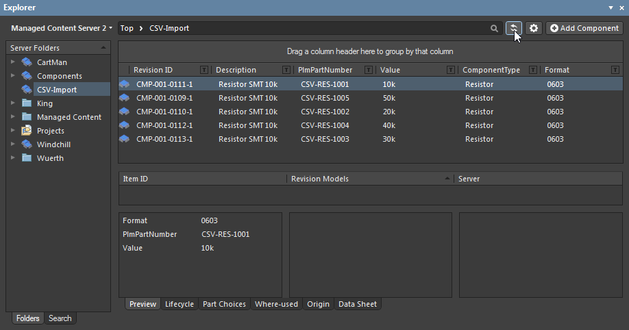
When used without applying a configuration file (option –c) the tool process will attempt to match the target CSV filename (say, Resistor.csv) with a server Component Template that supports that Component Type (Resistor). The found Template will determine the Revision, Lifecycle and Default Folder (server target) for the imported data. Note that the minimum data requirement for the source CSV file is the PART_NUMBER parameter column and its matching Values.
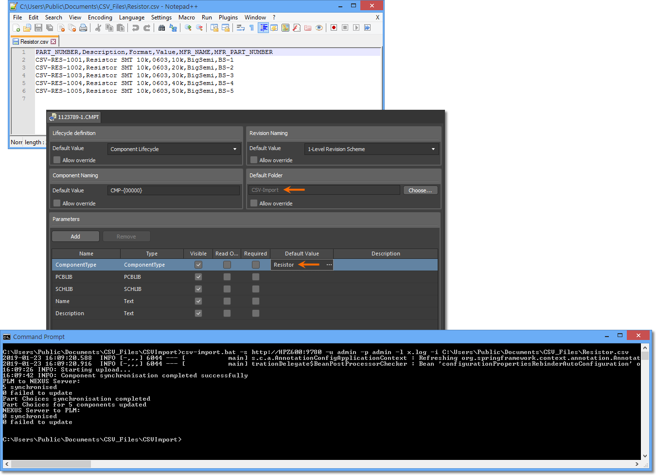
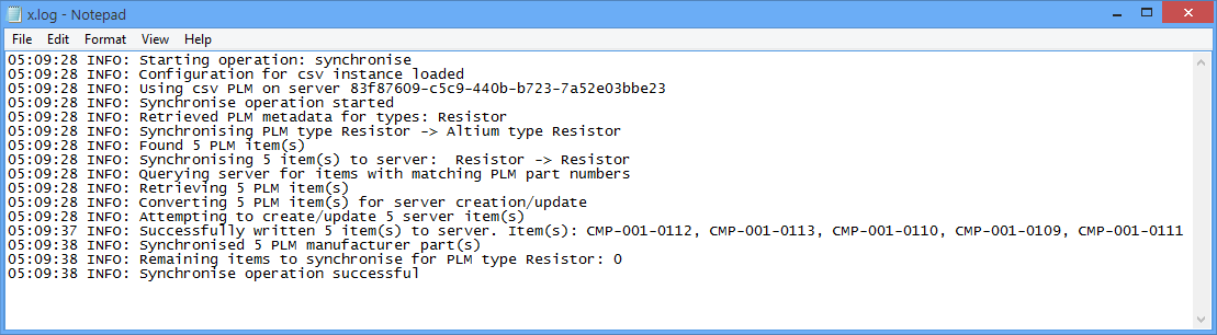
The csv-import utility tool provides general progress information in the console window as it runs, and can also produce a log file as specified by the command syntax (-l). If component manufacturer part parameters are present in the CSV file (by default; MFR_PART_NUMBER and MFR_NAME), matching Part Choice entries are created in the server.
The optional log file provides details of a successful import process – if the process fails, a log file is not generated.
Configured mode
The tool’s more advanced mode uses an XML configuration file to specify file-to-server parameter mapping for the import process. For the example shown here this might be say, mapping the source Value parameter to Resistance in the server, and the Format parameter to Package.
To obtain a base configuration file that can be modified to suit, run the tool with the generate configuration file setting (-g). This will create the specified XML file with parameter key/value pairs extracted from the source CSV file, and the Revision, Lifecycle and target folder setting from the matched Template. For example:
csv-import.bat -s http://HPZ600:9780 -u admin -p admin -g MyConfig.xml -i C:\Users\Public\Documents\CSV_Files\Resistor.csv
Edit the Attribute Values in the ToAltium section of the MyConfig.xml configuration file (for the Resistor PLM class) to map as required.
Mapping edits for this exampleExpand折りたたむ
For the example shown here, the related Attributes would be changed from:
<ns2:Attribute attributeType="revision">

  <ns2:Key>Format</ns2:Key>

  <ns2:Value>${attribute.Format}</ns2:Value>

</ns2:Attribute>

<ns2:Attribute attributeType="revision">

  <ns2:Key>Value</ns2:Key>

  <ns2:Value>${attribute.Value}</ns2:Value>

</ns2:Attribute>
...to:
<ns2:Attribute attributeType="revision">

  <ns2:Key>Package</ns2:Key>

  <ns2:Value>${attribute.Format}</ns2:Value>

</ns2:Attribute>

<ns2:Attribute attributeType="revision">

  <ns2:Key>Resistance</ns2:Key>

  <ns2:Value>${attribute.Value}</ns2:Value>

</ns2:Attribute>
The configuration file is then used with the tool (option –c) to perform the required mapping:
csv-import.bat -s http://HPZ600:9780 -u admin -p admin -c MyConfig.xml -i C:\Users\Public\Documents\CSV_Files\Resistor.csv
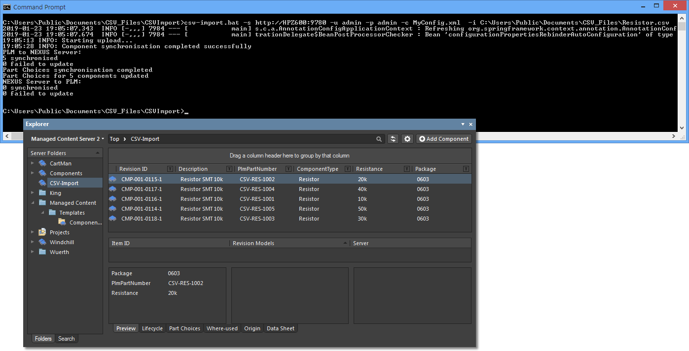
If the component entries already exist in the Server (as imported in the above
Auto mode example process), new Revisions will be created and the remapped parameters added to the existing data – existing parameters are not removed.
Additional features:
- An applied configuration file determines all settings for the import process, including parameter mappings, independently of related server Templates.
- All parameters may be mapped to accommodate the input CSV file parameters, including what name is used in the file for PLM Number and the part manufacturer data.
- Multiple Entity definitions, including their constituent parameter Attributes, can be included in a configuration file. Copy an existing Entity group entry, say for
Resistor, and then paste/edit this to create another for Capacitor.
- When a source path is specified without a CSV file, the tool will search the source folder for CSV filenames that match Entity definitions in the configuration file. So if configuration Entity references exist for
Capacitor and Resistor and matching CSV files are found, the data for those components will be imported into the server. This is effectively the tool's batch operation mode.
- If the source CSV file uses a particular filename structure that does not match the standard server Component Types (
Resistor, Capacitor, etc), this can be allowed for by mapping the PLM class in the configuration file. For example if the source file is PLM-Export_Resistors.csv, the PLM class entry plmType=”Resistor” can be changed to plmType=”PLM-Export_Resistors”.
