
Working with a Designator Object on a Schematic Sheet in Altium NEXUS
This document is no longer available beyond version 4. Information can now be found here: Designator for version 5
Parent page: Schematic Objects
 The Designator uniquely identifies each component in the design.
Summary
The designator field is a child parameter object of a schematic component (part). It is used to uniquely identify each placed part to distinguish it from all other parts placed in all the schematic sheets in the project.
Availability and Placement
The designator is automatically placed when the parent component part object is placed. It is not a design object that you can directly place.
Graphical Editing
The designator string can be edited graphically using what is known as in-place editing. To edit a designator string in place, select the designator by dragging your cursor around it, then hit enter.

An example of in-place editing
Once editing is complete, press Enter or click away from the string to exit in-place editing mode.
Non-Graphical Editing
There are two aspects to consider in relation to editing the designator: editing the value of the designator and editing the display properties of the designator.
The designator (and comment) strings can be displayed in the schematic library editor then doubled-clicked on to edit the properties. The ![]() icon associated with the field in the Properties panel is used to show or hide the designator.
icon associated with the field in the Properties panel is used to show or hide the designator.
Editing the Designator Value in the Schematic Editor
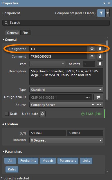
The designator can be defined in the schematic editor as the component is being placed or after the component has been placed on a schematic sheet in the Properties panel.
- To edit the designator during component placement, press the Tab key while the component is floating on the cursor. The Properties panel will open; enter the required designator string. Click the design space pause button overlay (
 ) to resume placement.
 - Continue to place components or press Esc to terminate placement.
- Press the Spacebar to rotate the arc counterclockwise or Shift+Spacebar for clockwise rotation. The action can also be performed while dragging the object. Rotation is in increments of 90°.
- To edit the designator after placement, double-click on the placed component to open the Properties panel where the designator can be edited.
Editing the Designator Display Properties
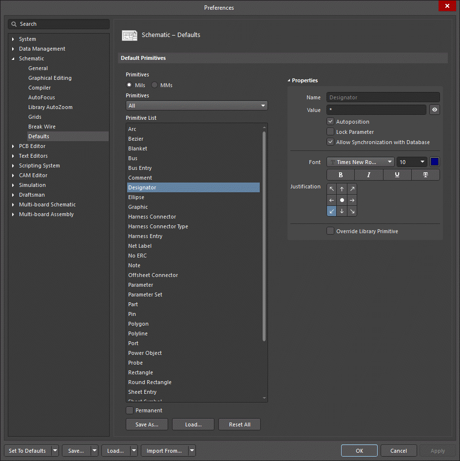
The appearance of the designator string, which includes the font type, size, and color, can be configured on the Schematic - Defaults page of the Preferences dialog. These settings will apply unless overridden by settings defined in the component symbol in the Schematic Library Editor.
The following methods of non-graphical editing are available:
Editing via the Designator Dialog or Properties Panel
Panel page: Designator Properties
This method of editing uses the associated Designator dialog and the Properties panel mode to modify the properties of a designator.
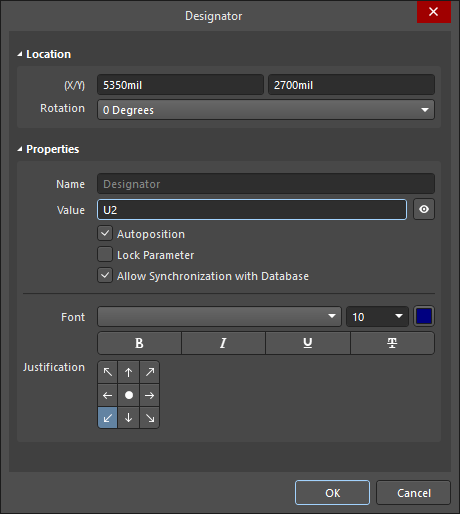
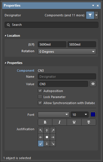 The Designator dialog, on the left, and the Designator mode of the Properties panel on the right
After placement, the Designator dialog can be accessed by:
- Double-clicking on the placed designator object.
- Placing the cursor over the designator object, right-clicking, then choosing Properties from the context menu.
After placement, the Designator mode of the Properties panel can be accessed in one of the following ways:
- If the Properties panel is already active, by selecting the designator.
- After selecting the designator, select the Properties panel from the Panels button in the bottom right section of the design space or select View » Panels » Properties from the main menu.
Editing Multiple Objects
The Properties panel supports multiple object editing, where the property settings that are identical in all currently selected objects may be modified. When multiples of the same object type are selected manually, via the Find Similar Objects dialog or through a Filter or List panel, a Properties panel field entry that is not shown as an asterisk (*) may be edited for all selected objects.
Editing via a List Panel
Panel pages: SCH List, SCHLIB List, SCH Filter, SCHLIB Filter
A List panel allows you to display design objects from one or more documents in tabular format, enabling quick inspection and modification of object attributes. Used in conjunction with appropriate filtering - by using the applicable Filter panel, or the Find Similar Objects dialog - it enables the display of just those objects falling under the scope of the active filter – allowing you to target and edit multiple design objects with greater accuracy and efficiency.
Fixing the Location of the Designator String
The default behavior of the Designator is to auto-position it as a component is rotated during placement. If this behavior is not required, turn off the Autoposition option in the Preferences dialog (refer to the previous image) either during symbol creation or after the component has been placed on a schematic sheet. Note that doing this sets this parameter to be classified as a manual parameter (meaning manually positioned parameter). Manual parameters are identified by a dot on the lower left corner of their selection box.
Notes
- The Schematic Editor includes a simple auto-increment feature for the designator that can be used during the placement of multiple instances of the same part. To use this, press Tab while the first component is floating on the cursor and enter a suitable designator, for example
R1. Subsequent components will then be designatedR2,R3, etc. Note that when you switch to placing a different component type you must again press Tab and enter a suitable designator prefix. - When placing multi-part components and the initial designator is assigned as just described, a part suffix will automatically be assigned, for example,
U3A,U3B, etc. If the initial designator is not assigned, all parts will have the same suffix. This is resolved by the Schematic Editor's Annotation command. The part suffix can be alpha or numeric. Use the Alpha Numeric Suffix option on the Schematic - General page of the Preferences dialog to configure.