
KB: Duplicate Designators in Multi-Channel Designs Caused by Incorrect Sheet Symbol Parameters
 Altium Designer
Solution Details
Duplicate Designators Affect Specific Design Channels
A hierarchical schematic design containing six channels showed duplicate component reference designators in channels 5 and 6, while channels 1 through 4 annotated correctly. The issue was traced to the parametric multi-channel configuration. A Sheet Symbol parameter associated with Channel 5 incorrectly referenced the identifier used by Channel 4, resulting in annotation conflicts.
Component annotation assigns unique designators so components can be identified consistently throughout the design and associated outputs.
Incorrect Parameters Prevent Channel Differentiation
In a multi-channel design, repeated circuitry is captured once and expanded into physical channel instances during compilation. Channel naming and annotation settings are then used to identify the resulting instances.
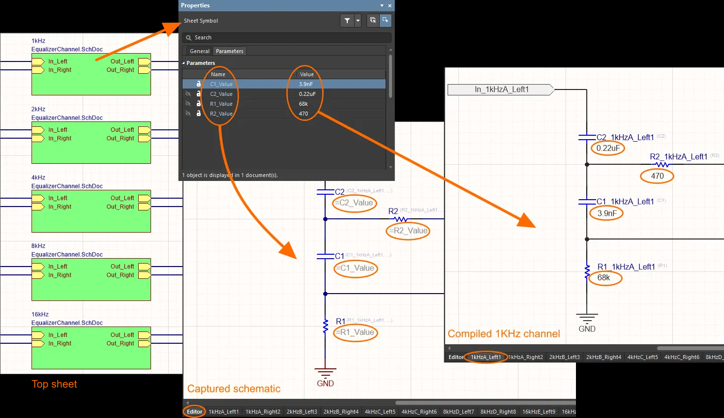
Sheet Symbol parameters can provide channel-specific parameter values. In this case, an incorrect channel-specific value prevented the affected channel instances from being differentiated as intended and resulted in conflicting component designators. Not every duplicated Sheet Symbol parameter necessarily causes duplicate annotation; the relevant parameter and how it is used in the parametric design must be checked.
Correct Parameters or Override Physical Designators
- Correct the affected Sheet Symbol parameters so each channel has the intended unique channel-specific value, then rerun schematic annotation.
- Use Board-Level Annotation when physical designators require a controlled naming scheme or specific custom values. This method is particularly useful for multi-channel designs and can resolve conflicting physical designators without changing the underlying logical designators.
Update Parameters and Reapply Component Annotation
Method 1: Correct the channel parameters
- Open the parent schematic containing the hierarchical Sheet Symbols.
- Select the Sheet Symbol for the affected channel, such as Channel 5.
- Open the Properties panel, or right-click the Sheet Symbol and select Properties.
- In the Parameters section, locate the parameter controlling the required channel-specific value, for example, U_1_PartReference.
- Check the parameter for duplicated or incorrect values.
- Update the parameter to the intended unique channel-specific value. For example: Amplifier_channel5_U_1_PartReference.
- Save the schematic.
- Select Tools » Annotation » Annotate Schematics.
- Run the annotation and confirm that component reference designators are unique across all channels.
Method 2: Manually override designators using Board-Level Annotation
- Open the PCB project.
- Select Tools » Annotation » Board Level Annotation.
- Expand the channel list and locate the component whose physical designator requires manual control.
- Disable Apply Naming Scheme for the component.
- Enter the required designator manually.
- Select Generate ECO.
- Review the proposed changes and select Execute Changes in the ECO dialog.
- Verify that the required physical designators have been applied.
Additional Notes
- Board-Level Annotation changes are stored in a project annotation file with the .Annotation extension. These physical annotation settings can override logical designators when the design is compiled and transferred to the PCB.
- If the Sheet Symbol parameters have been corrected but unexpected physical designators remain, check whether Board-Level Annotation was previously applied. An existing .Annotation file can continue to affect compiled component designators.
- Do not remove an existing .Annotation file solely because physical and logical designators differ. First determine whether Board-Level Annotation was intentionally configured for the project.