
KB: Create a Polygon from a DXF Outline
Updated: November 11, 2026
 Altium Designer
This article explains how to import a DWG or DXF file and create a polygon from the imported outline. It also covers situations where multiple objects, inner polygons, or intersecting shapes are present in the imported drawing. By converting selected primitives into a polygon and, when necessary, breaking object unions before conversion, users can create accurate polygon shapes based on DWG/DXF geometry.
Solution Details
Imported Geometry Requires Polygon Conversion
In some situations, a precise polygon shape is required from geometry defined in a DWG or DXF file. After importing the drawing, the geometry is represented as primitives rather than a polygon and must be converted before it can be used as a polygon shape.
Multiple Objects Can Affect Conversion Results
A DWG or DXF file may contain multiple separate shapes, inner and outer outlines, or intersecting polygons. These conditions can prevent the creation of the desired polygon if the imported objects remain grouped together or contain object unions.
Prepare Imported Objects for Polygon Creation
- Import the DWG or DXF file using the appropriate import command.
- Create a polygon directly from the imported primitives when only a single outline is required.
- Break object unions before conversion when multiple shapes or intersecting inner and outer polygons are present.
- Remove imported primitives after conversion if they are no longer needed.
Import and Convert the Drawing Geometry
- Import the DWG or DXF file by selecting File » Import » DXF/DWG.
- If available, confirm the actual size of the drawing to help prevent scaling issues during import.
- Select the appropriate import settings and complete the import.
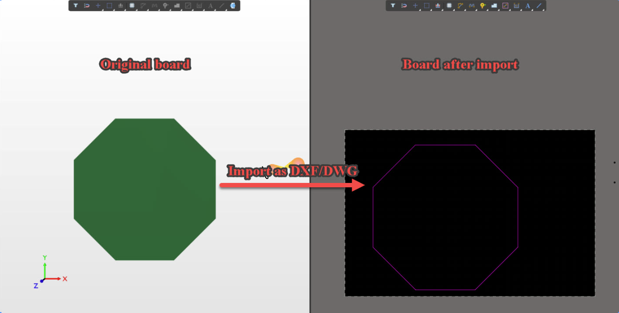
- Select all outside primitives that define the required shape.
- Navigate to Tools » Convert » Create Polygon from Selected Primitives to create the polygon.
- If the original imported primitives are no longer required, delete them after the polygon has been created.
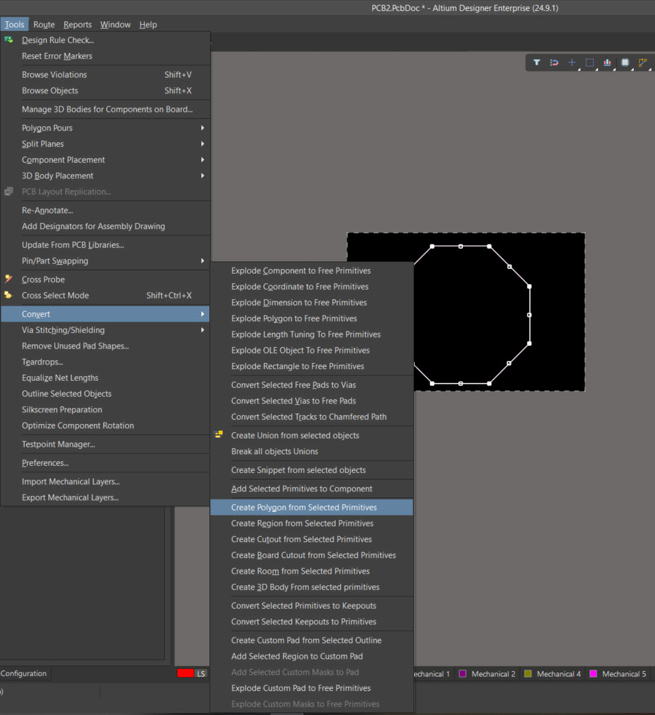
- If multiple polygons, intersecting outlines, or inner and outer polygons prevent the desired result, select the affected objects.
- Navigate to Tools » Convert » Break All Object Unions.
- Separate the required objects as needed.
- Repeat Tools » Convert » Create Polygon from Selected Primitives to generate the correct polygon.
Additional Notes
Once a polygon has been successfully created, the original imported DWG/DXF primitives remain in the design and can be removed if they are no longer required.