
KB: Signal Length Displays as 0 or NA for Nets in the PCB Panel
 Altium Designer
Solution Details
Signal Length Values Missing in PCB Panel
Users may notice that signal length values are not calculated for certain nets in the PCB panel, resulting in values of 0 or "n/a". This can limit visibility into signal path metrics used for high-speed PCB design analysis, timing verification, and length matching.
Conditions That Prevent Signal Length Calculation
Signal length calculations are subject to specific requirements within the PCB editor.
- Signal length is only calculated for nets with exactly two nodes.
- Nets with more than two nodes display 0.
- Nets governed by Supply Nets design rules are excluded from signal length and signal delay calculations and display "n/a".
- Supply Nets rules may be automatically recreated during ECO synchronization from the schematic, depending on preference settings.
Available Options to Enable Length Analysis
- Verify the node count of the affected net.
- Define xSignals for nets that contain more than two nodes or span multiple connected nets.
- Review and remove the Supply Nets rule if signal length analysis is required.
- Disable automatic generation of Supply Nets rules if they are being recreated during ECO updates.
Review Net Configuration and Restore Calculations
-
Understand the difference between Routed Length and Signal Length.
- Routed Length: The sum of placed track and arc segments plus vertical via distances. It does not resolve overlapping segments or routing inside pads.
- Signal Length: The accurate node-to-node distance. It resolves overlapping objects, includes via lengths, and uses Manhattan length for unrouted nets.
The PCB panel can display both measurements. Routed Length reflects the physical routing that has been placed, while Signal Length represents the actual point-to-point signal path used for timing-related analysis.
-
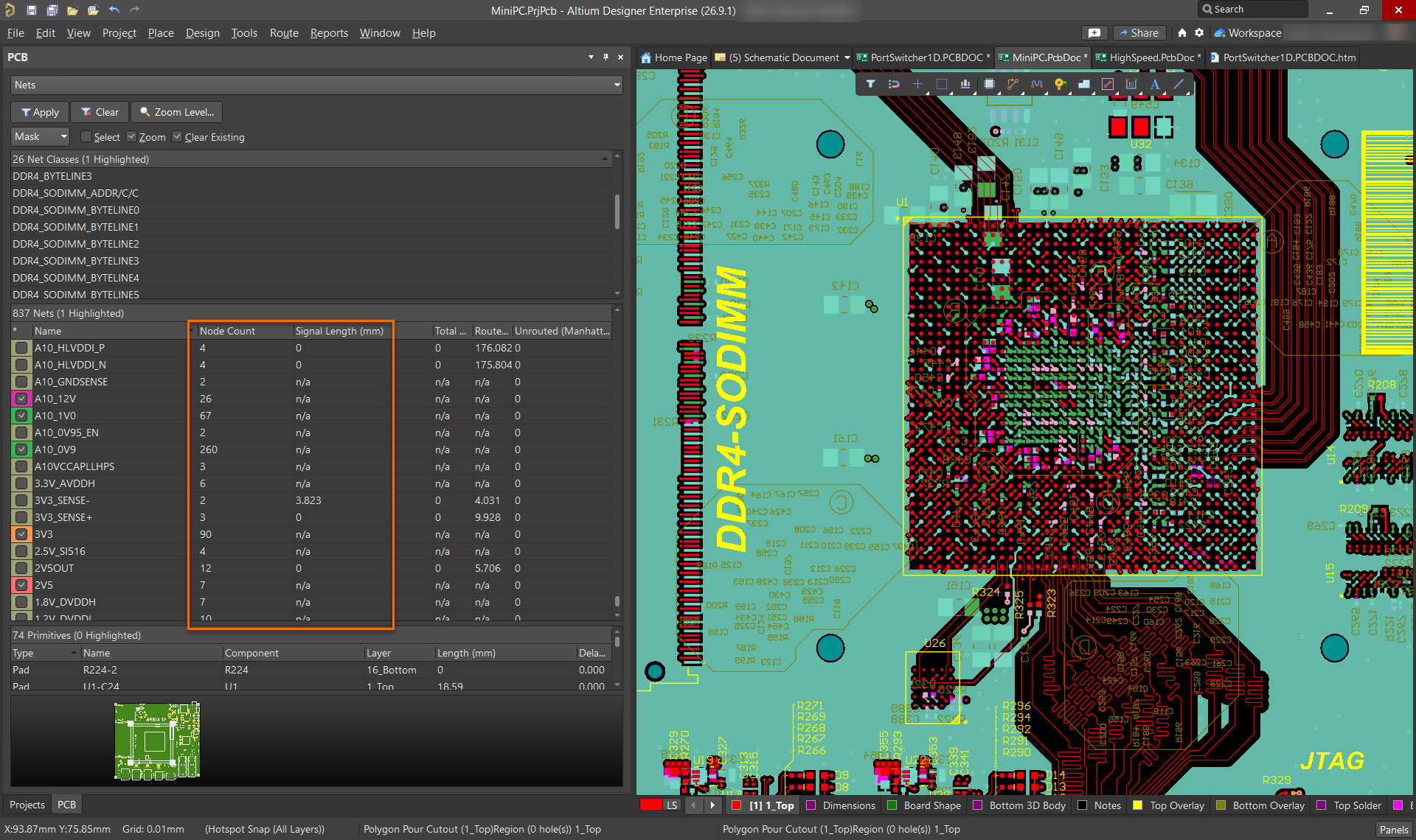
Check the node count in the PCB panel.
- Select Panels » PCB.
- Select Nets from the panel drop-down.
- Select All Nets.
- Click the Signal Length column header to sort.
- Review the Node Count column.
Note: Signal length is only calculated for nets with exactly two nodes. Nets with more than two nodes will display 0.
-
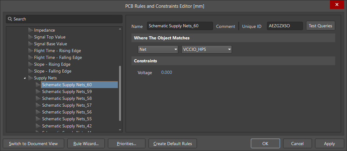
Review and remove the Supply Nets rule if required.
- Select Design » Rules.
- Navigate to Signal Integrity » Supply Nets.
- Check whether the affected net is included in the rule.
- Remove the rule association if signal length calculation is required.
Note: The Supply Nets rule may be recreated during an Engineering Change Order (ECO) update from the schematic. By default, a Supply Nets rule for power nets is automatically generated when the advanced preference Schematic.AutoGenerateSupplyNetsRule is enabled.
To disable automatic Supply Nets rule generation:
- Open Preferences and navigate to System » General.
- Select Advanced... and search for Schematic.AutoGenerateSupplyNetsRule.
- Disable the setting, apply the changes and perform the ECO again if required.
-
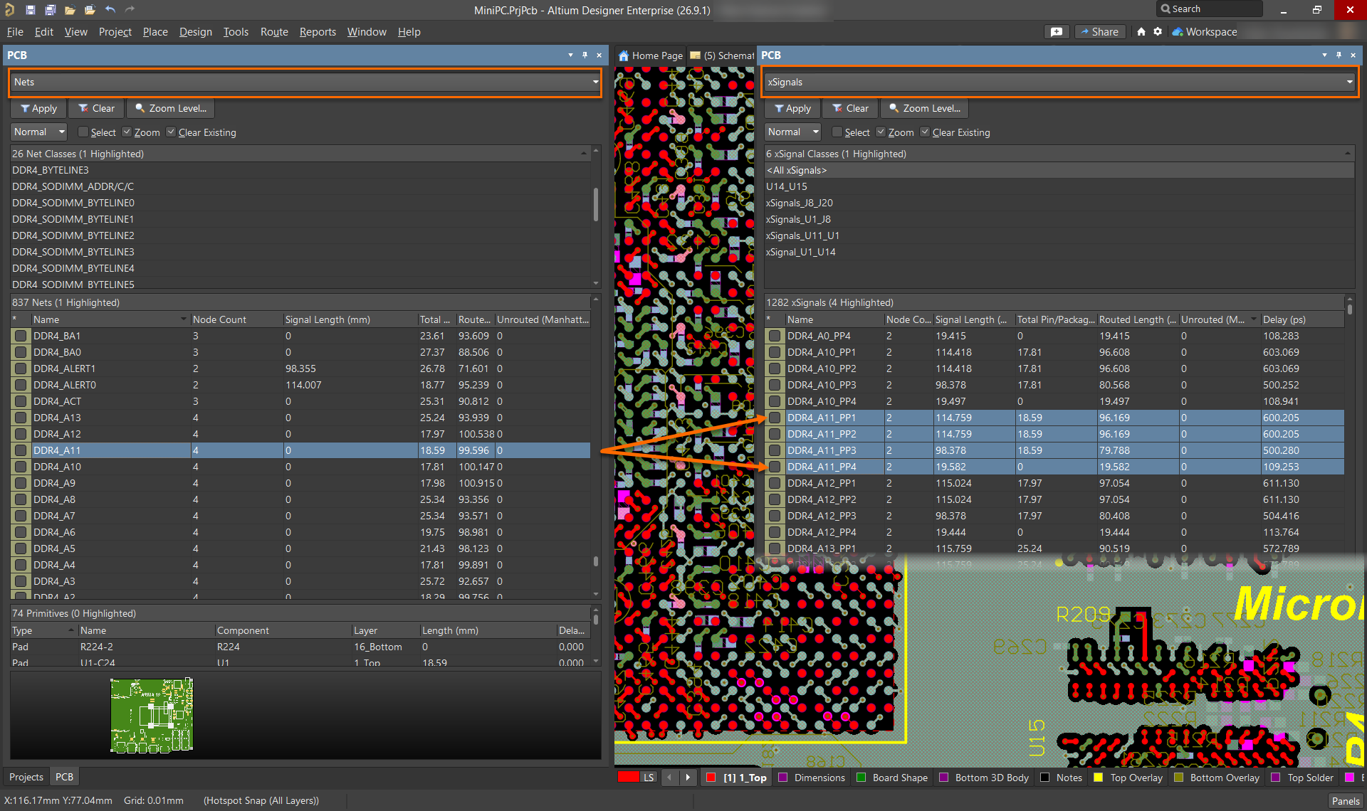
Define xSignals for multi-node nets.
- Identify nets with more than two nodes.
- Define xSignals for the required signal paths.
- Verify that signal length values are now available for the defined xSignals.
An xSignal is a designer-defined signal path between two nodes. The path can exist within a single net or span multiple nets connected through components such as series termination resistors. xSignals allow signal length calculations to be performed on complex signal paths that cannot be represented by a single two-node net.
Common use cases include:
- Memory interfaces such as DDR routing.
- Fly-by and balanced-T routing topologies.
- Signal paths that include series termination components.
- Any branched net requiring accurate point-to-point length analysis.
Additional Notes
- Signal length is a point-to-point metric and is not applicable to branched nets unless xSignals are defined.
- Power nets typically do not require signal length analysis and are excluded from calculation by default.
- The default value of Schematic.AutoGenerateSupplyNetsRule is enabled, which causes Supply Nets rules to be automatically generated during ECO for power nets.
- Supply Nets rules exclude both signal length and signal delay calculations for the affected nets.