Schematic Capture Improvement
Added Violation Checks for Objects Connected to a Harness Connector
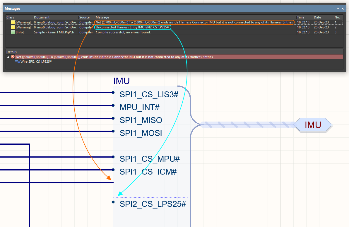
In this release, new violation checks have been added to detect violations associated with signal harnesses in the schematics of your PCB design projects:
- The Invalid Connection to a Harness Connector violation check detects a situation when a wire, bus, or signal harness ends inside or is connected to the edge of a harness connector but is not connected to a harness entry.
- The Unconnected Harness Entry violation check detects an unconnected harness entry.
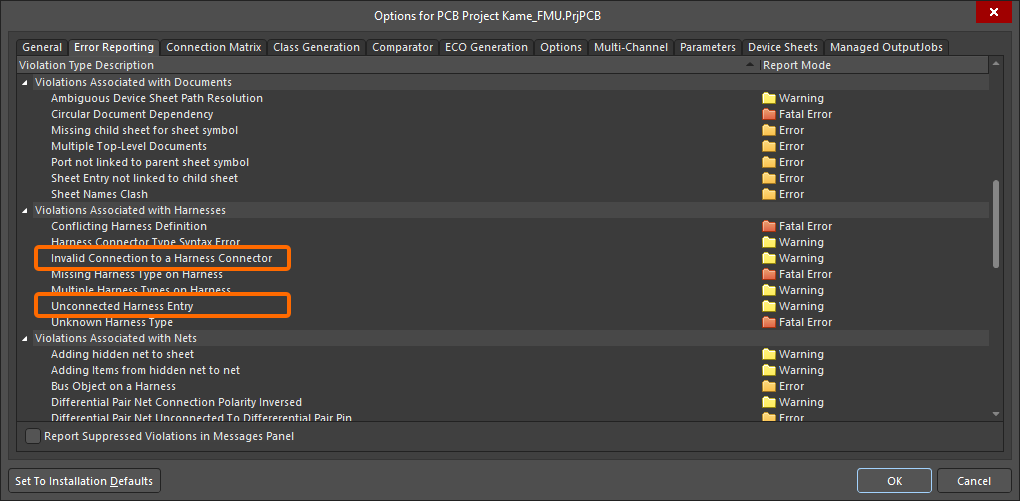
Settings for these violation types can be found in the Violation Associated with Harnesses group on the Error Reporting tab of the Project Options dialog.
PCB Design Improvements
Pad Hole Clearance Check Improvement (Open Beta)
In this release, the behavior of detecting clearance from pads with no annular ring has been improved.
When a pad has a hole size greater than or equal to the pad size and, therefore, has no annular ring, the clearance value defined for the Hole by the applicable constraint in the Constraint Manager or by the Clearance design rule is applied rather than the maximum of Hole and TH Pad clearances.

An example of clearances configured in the Constraint Manager.

An example of clearances configured in the Clearance design rule.

The new pad hole clearance behavior.
Note that the default values of Hole clearance in newly created Clearance constraints and Clearance design rules have been updated with the 10mil / 0.254mm value.
This feature is in Open Beta and available when the
PCB.Rules.HoleClearance option is enabled in the
Advanced Settings dialog.
Ability to Store TrueType Fonts (Open Beta)
This release has added the ability to automatically store geometries of text objects that use TrueType fonts inside PCB documents. When objects (text strings/frames, dimensions, drill tables, and/or layer stack tables) in a PCB document use a TrueType font, these objects will be shown using the same font geometry when the PCB document is opened on another computer, even if that TrueType font is not installed.
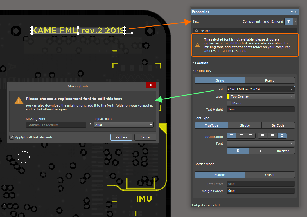
When an object that uses a missing font is selected, a warning message appears at the top of the Properties panel. When changing object properties that affect its text (e.g., the text height or text itself), the Missing fonts dialog opens in which you can select a replacement font.
The dialog also appears when changing text-related properties from the PCB List panel.
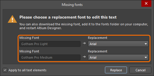
When trying to edit multiple objects using different missing fonts, the dialog allows you to select a replacement for each missing font.
This feature is in Open Beta and available when the PCB.Text.TTFontSaving option is enabled in the Advanced Settings dialog.
Note that with this feature enabled, the options of the PCB Editor – True Type Fonts page of the Preferences dialog are no longer relevant, so this page is not available in the Preferences dialog (when the PCB.Text.TTFontSetting.Hide option is enabled in the Advanced Settings dialog).
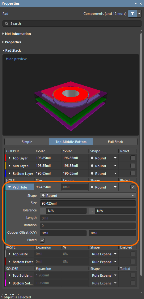
Enhanced Pad Properties Panel
The Pad Stack region of the Pad Properties panel has been enhanced for better usability. When a section is selected, the section name is highlighted in blue and the entire section is displayed in a different shade than the background.
PCB CoDesign Improvements
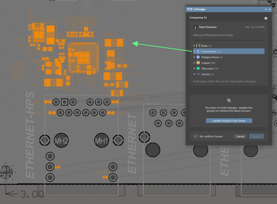
Ability to Highlight Category Changes
With the Show on PCB option enabled in the PCB CoDesign panel, you can now highlight all changes in a specific category when that category is selected in the panel's list of changes.
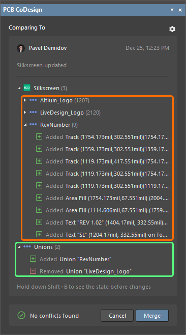
Grouping Changes by Unions
Added support for comparison of, and application of changes to, unions (defined groupings of primitives on the PCB). Union-related changes are shown in the Unions category in the PCB CoDesign panel's list of changes. Also, changes in other categories are grouped now by unions if corresponding objects belong to any.
Updates to 'Merged' State
After merging changes using the PCB CoDesign panel, the PCB document will remain in the Merged state (the  icon in the Projects panel) until there is a new conflict. Saving changes locally will no longer change the state to Modified.
Also, note that documents in Merged state are always enabled for saving to the Workspace in the Save to Server dialog and cannot be disabled.
Constraint Manager Improvements
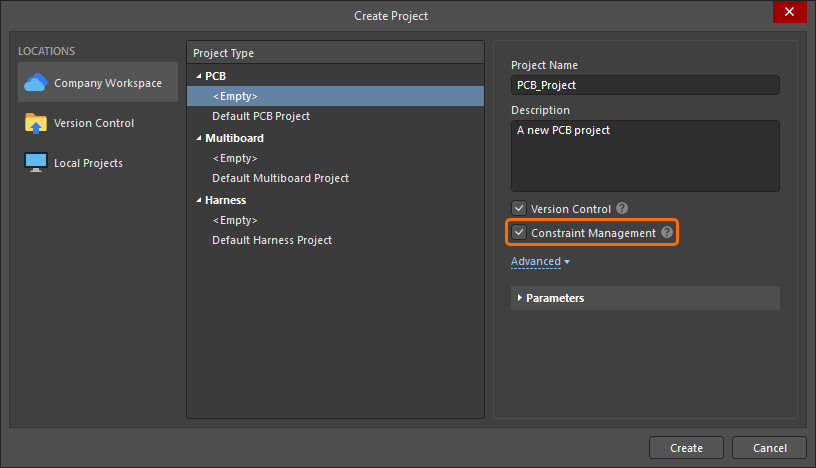
Ability to Choose Usage of the Constraint Manager for a New Project
When creating a new PCB project, you now have the ability to control whether it will use the Constraint Manager or the older design rules system. In the Create Project dialog (File » New » Project), enable the Constraint Management option to use the Constraint Manager for the project being created.
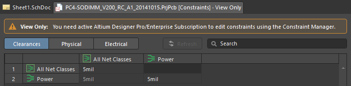
'View Only' Mode
If the Constraint Manager was enabled for the PCB project, the Constraint Manager will present in View Only mode when opened by a user without Altium Designer Pro/Enterprise Subscription. In this case, the user can see, but not modify, defined constraints. The message at the top of the Constraint Manager notifies you when the Constraint Manager is in View Only mode.
Updates to xSignal Creation
This release sees some updates in defining xSignals using the Constraint Manager:
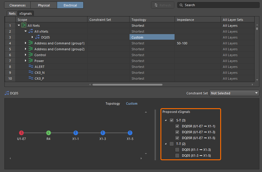
- The list of proposed xSignals is now divided into two groups: xSignals going from a source to a destination point (S-T) and xSignals going from one destination point to another (T-T). Use checkboxes for groups to select/deselect all xSignals in corresponding groups.
- The list of proposed xSignals now includes xSignals going from a source to each destination (not an xSignal going from a source to the closest destination only).
-
For a better representation of proposed xSignals, they are now named in the list using the following scheme:
<SourceNetName> (<SourcePinDesignator> → <DestinationPinDesignator>)
Note that for names of created xSignals that can be seen on the xSignals tab to the Constraint Manager or in the PCB document, the previous <SourceNetName>_<SourcePinDesignator>_<DestinationPinDesignator> scheme is used.
Improved Class Selection
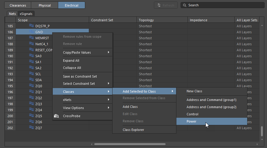
The right-click menu of entries in the Physical and Electrical views has been updated to quickly add objects to an existing class right from the menu. To do this, right-click one or more selected objects and choose an existing class from the Classes » Add Selected to Class sub-menu.
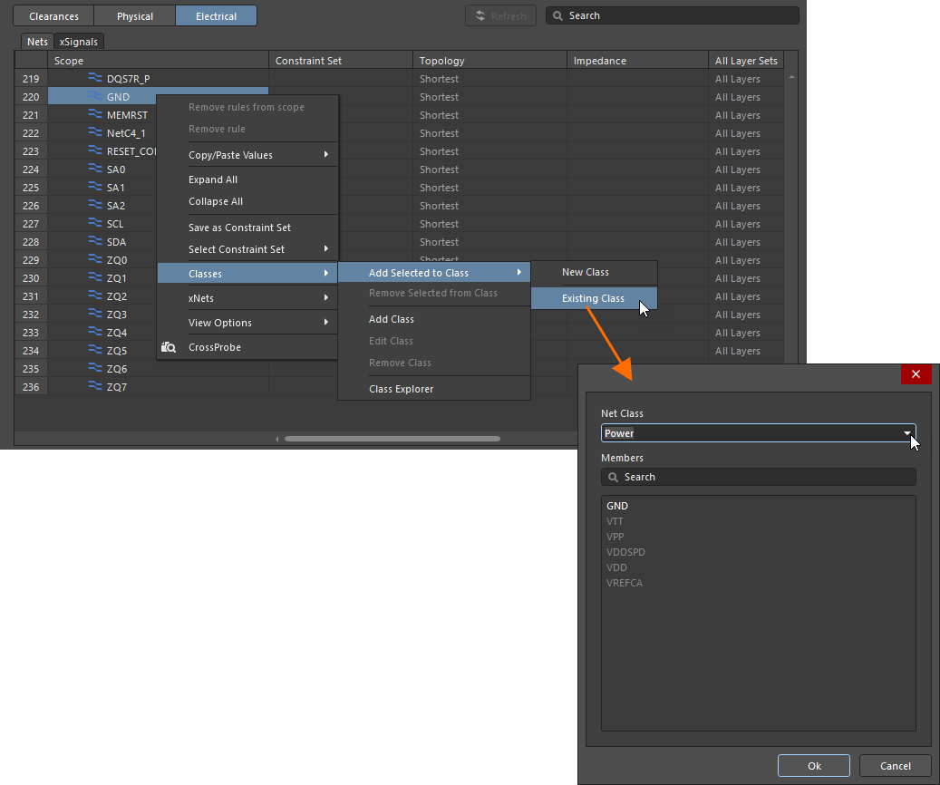
When there are more than 30 classes, the Classes » Add Selected to Class » Existing Class command is available in the menu instead of the list of classes. Use this command to access a dialog where you can select an existing class to which the selected object(s) are to be added.
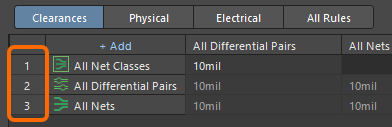
Added Line Numbers in Grid
Line numbers have been added to the Constraint Manager grid to help you more easily identify and distinguish items in the list.
Multi-board Design Improvements
Support for Draftsman Documents in Multi-board Projects (Open Beta)
You can now add a Draftsman document (*.MbDwf) to a Multi-board project to create a manufacturing drawing for the Multi-board assembly in this project.
The views that can be placed in a Draftsman document of a Multi-board project are:
- Multi-board view – an automated graphic composite of the outlines of PCBs and 3D models constituting the multi-board assembly.
- Section view – a profile slice, or sectional, drawing taken from a nominated 'cut' point through a placed multi-board view.
- Board detail view – a floating, magnified view of a multi-board view's defined area.
- Board realistic view – a scalable 3D rendering of the current multi-board assembly.
Draftsman's annotation, dimensioning and graphical tools, as well as BOM and generic tables, are also available.

An example of a Multi-board project Draftsman drawing.
Ability to Move a Module Entry Group
The ability to move a selected group of module entries in a multi-board schematic document (*.MbsDoc) has been added. This new feature speeds up the editing process by not requiring you to move each module entry individually. In the design space, select more than one module entry, then use the left mouse button to drag the group to the desired location. A red dot displays at each entry while they are dragged to the new location. Release the mouse button to place the group at the current location.
Harness Design Improvements
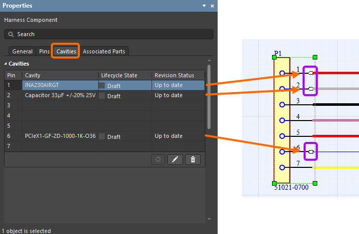
Changed 'Crimps' to 'Cavities'
'Crimps' have been renamed 'Cavities' in the UI of the Wiring Diagram and Layout Drawing.
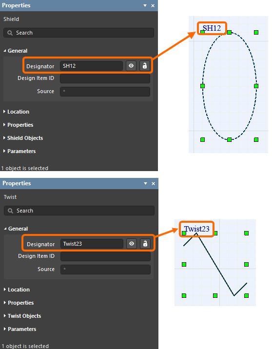
Added Designator Field to Shield and Twist Objects
The Designator field has been added to the properties of shields and twists in the harness wiring diagram.
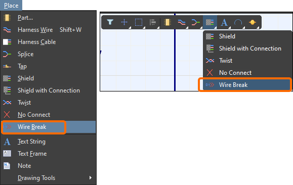
Added Wire Break Object for Multiple Sheet Capability
A full Wiring Diagram can now be defined over multiple sheets (in a 'flat' design fashion), each represented by its own *.WirDoc document, with the ability to split a wire using the new Wire Break object.
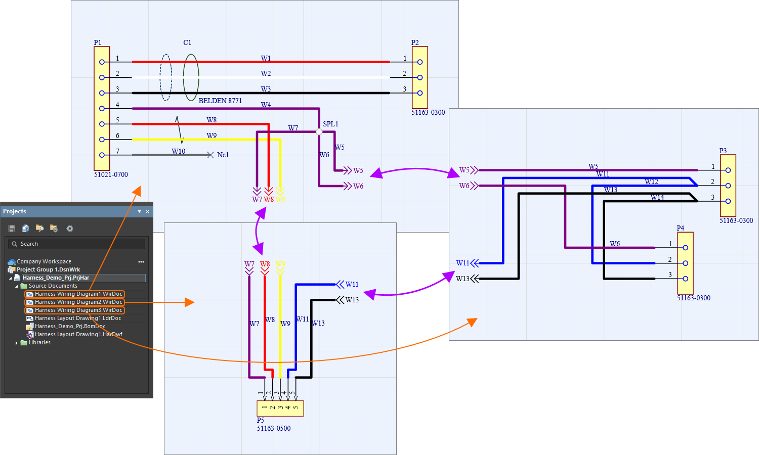
A Wire Break is placed using the Place menu or from the Active Bar as shown below.
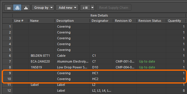
Treat Coverings as Components in BOM
Harness coverings in the Layout Drawing are now treated as components in the BOM, with support for part choices and grouping.
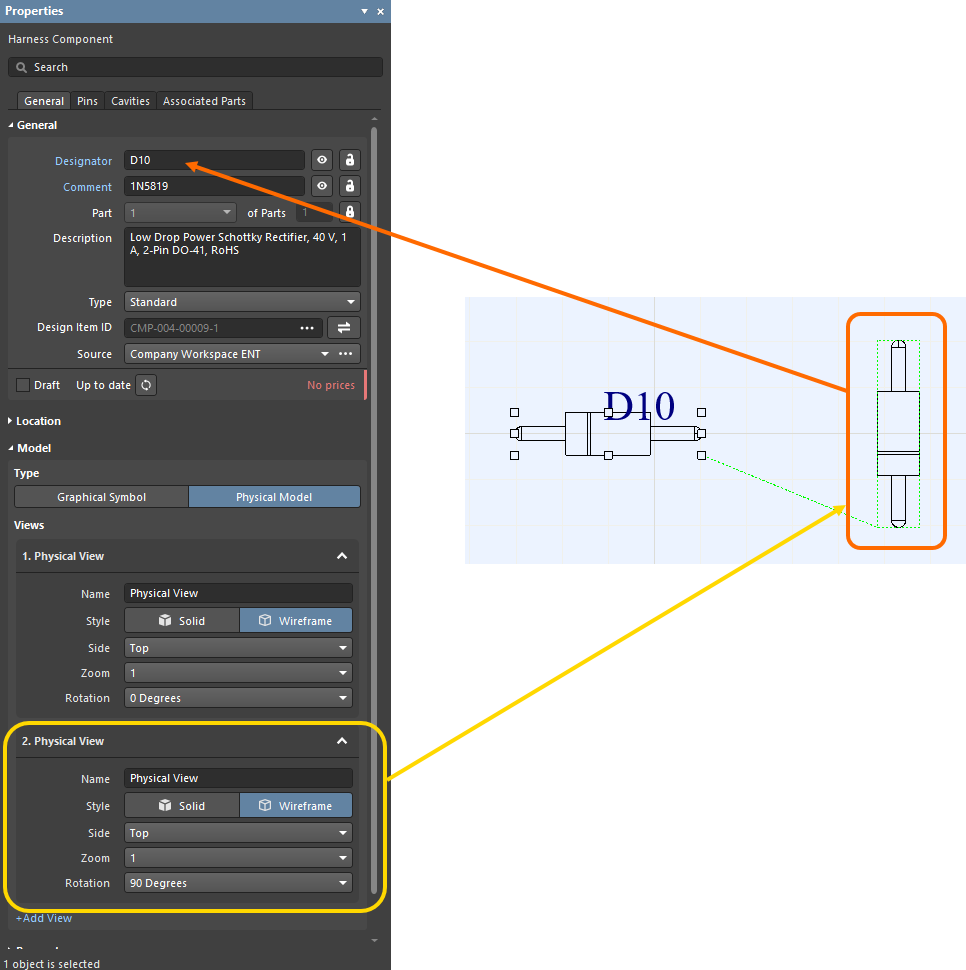
Display Component Properties for Additional Physical Views
When an additional physical view of a harness component is selected in the design space, the Properties panel now displays the properties of the component itself as it does for the main (first) physical view. In the below image, a second physical view has been selected in the design space; the Harness Component Properties panel displays the properties of the original (first) physical view.
Improved the Wiring List
Added Ability to 'Split' Wiring List
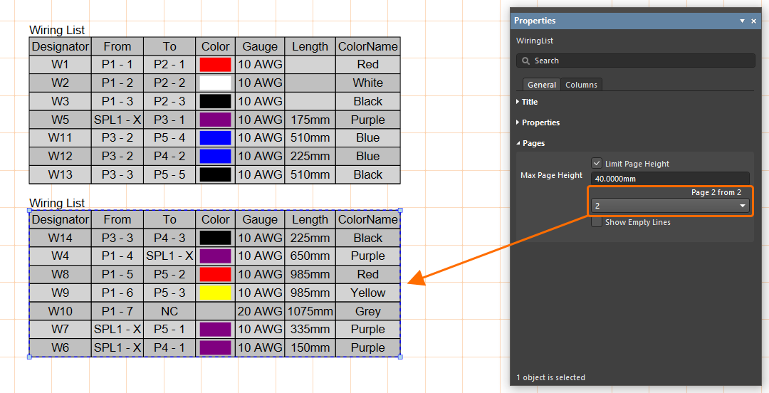
The wiring list of an advanced harness design may have a large number of entries, which can be difficult to fit into a drawing document as a single table. Rather than resorting to font and table scaling, multiple custom table entries, or an external document, you now have the ability to 'split' a Wiring List in a Harness Draftsman document so that the Wiring List will be presented over a number of 'pages.' In the Properties panel for a placed Wiring List, enable the Limit Page Height option in the Pages region to use the new feature. This will restrict the height of the Wiring List table to the nominated height entry (Max Page Height) and, therefore, the number of lines shown in the table.
❯ ❮
Javascript ID: Harness_MD_WiringList_LimitPageHeight
|
The editor detects that the entire Wiring List is not shown, as indicated by the panel's Page entry (for example, 1 from 2), and the associated drop-down menu allows you to nominate which page is shown. To add further pages of the Wiring List, place another Wiring List (Place » Wiring List) and specify the next Page in the Pages region of the Properties panel.
Enhanced Wiring List for 'Shield with Connection' Objects
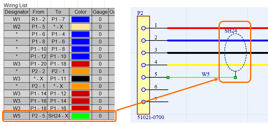
Designators of shield with connector objects are now displayed in the Wiring List when a wire is connected to the shield's connector.
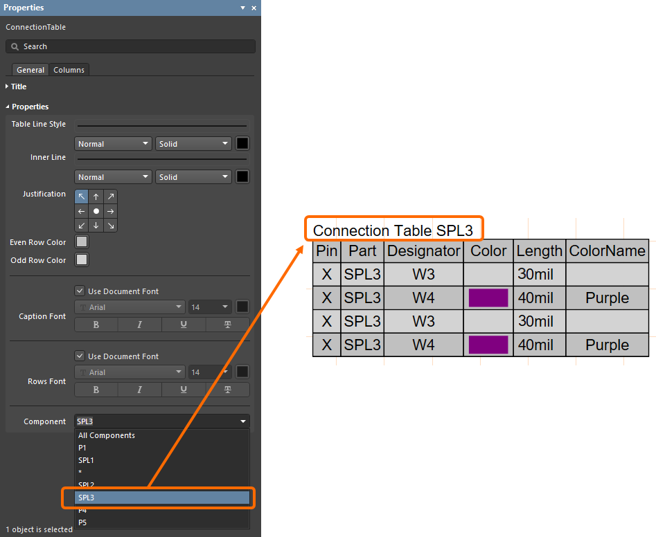
Added Ability to Display Connection Table for Splices
The ability to show the connection table for individual splices has been added. Previously, the ability to show the Connection Table for only components and connectors was possible.
Links Added to Text Frame and Note Objects for Cross-Probing
Object designators can now be added as active links in text frames and notes. The links provide cross-probe capabilities in the Wiring Diagram and Layout Drawing. To create active links, place a text frame or note object in either the Wiring Diagram or Layout Drawing. In the Text field in the Properties region of the Properties panel, enter "@". A drop-down of all designators will appear. Double-click the desired designator from the li st; the link is created in the Text field and in the design space. Click the link in the design space to cross-probe to that object in the associated document (i.e., the document that is not currently active). The process is demonstrated in the video below.
Data Management Improvements
Manufacturer Lifecycle State Message Enhancement
When using the SiliconExpert integration functionality, manufacturer part lifecycle data can be obtained from different sources: Altium Parts Provider (powered by Octopart or IHS Markit®) and SiliconExpert. To provide better visibility of this lifecycle data from different sources, the lifecycle information from all available sources is now accessible.
When exploring manufacturer part data (e.g., an entry in the Manufacturer Part Search panel, a part choice of a Workspace library component, or a solution in an AcitveBOM document), hover the cursor over the manufacturer lifecycle state/bar or use the drop-down to see the lifecycle information from all sources in the tooltip.
❯ ❮
Javascript ID: ManufacturerLifecycle_MultipleSources_AD24_1
|
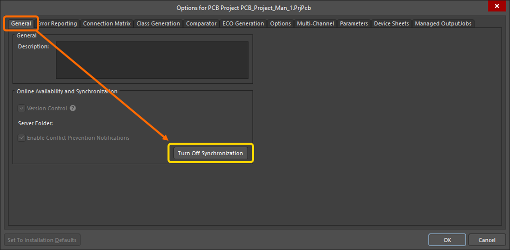
Added General Tab to Project Options for Offline Workspace Projects
Added the General tab to the Project Options dialog for offline Workspace projects. This feature is available for working with a project when you are disconnected from its Workspace. The only control on the tab that is accessible is the Turn Off Synchronization button. Click this button to turn off synchr onization. This ensures that the local copy will not be linked to the one that resides on the Workspace. The project located in the Workspace will remain untouched.
Removed Commit Command for Git-based Projects
For Git-based projects, the Commit command has been removed from the History & Version Control sub-menu of the right-click menu of project entry in the Projects panel and the Project main menu, aiming to remove confusion about where data was being committed (to the local repository and not the remote repository) when using the command. Visibility of the command is controlled by the VCS.AllowGitCommit option from the Advanced Settings dialog (OFF by default). You can use the Save to Server command to commit the project to the local repository and push it to the remote repository in one action.
Import/Export Improvement
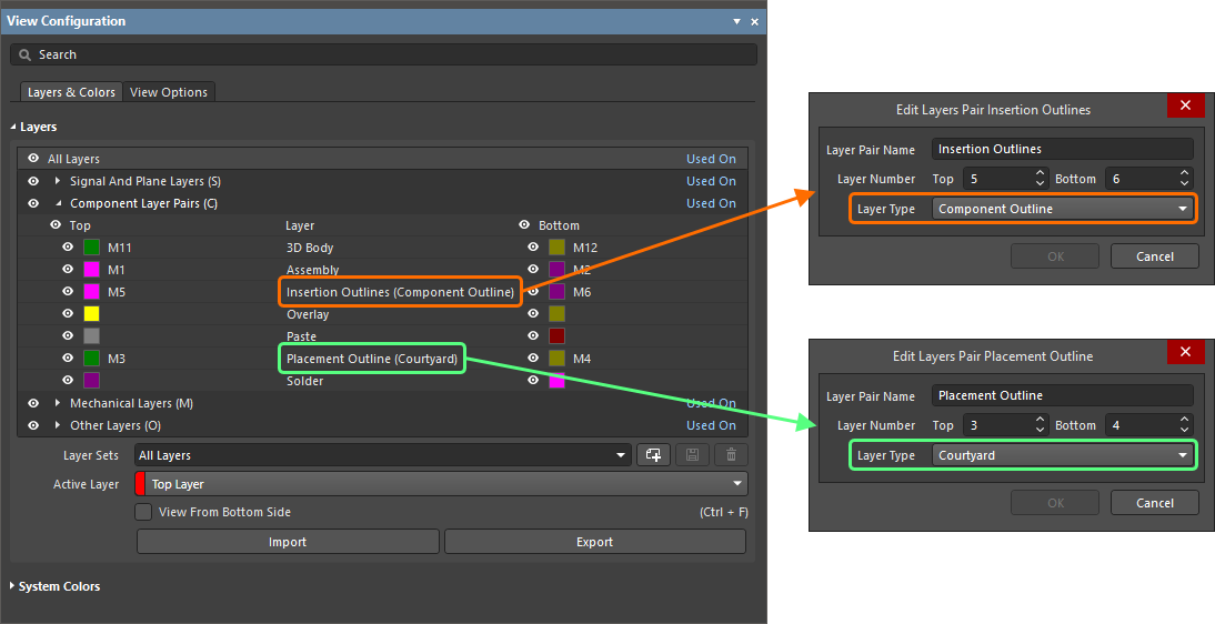
Mentor Xpedition Placement Outline and Insertion Ouline Layer Mapping
When Mentor Xpedition PCB and footprint library files are imported, Placement Outline layer types are now mapped as Courtyard layer types and the Insertion Outline layers are now mapped to the Component Outline layer types in Altium Designer.
Circuit Simulation Improvement
Simulation Stress Analysis (Open Beta)
Stress Analysis is used to calculate operating conditions for each individual component, such as maximum voltages, currents, and power dissipations, and check them against limits defined in the stress model of the component.
In this release, a new Stress Analysis option has been added to the Transient region of the Simulation Dashboard. When this option is enabled and the Transient analysis is performed, the Stress analysis results are available on the additional Stress chart of the simulation result document.

Use the new Stress Analysis to test your circuits against defined limits.
The stress model of a component is configured on the new Stress tab of the Sim Model dialog accessed for the component's simulation model. From here, you can select the required Device Type and define parameter values.

Stress analysis parameters for a component can be set on the Stress tab of the Sim Model dialog.
This feature is in Open Beta and available when the
Simulation.StressAnalysis option is enabled in the
Advanced Settings dialog.
Feature Made Fully Public in Altium Designer 24.1
The following feature is now officially made Public with this release:
