Parent page: PCB Design Objects

A PCB component footprint completed with a 3D Body.
Summary
A 3D body is a primitive design object that is used as a container into which a standard-format generic 3D model, including STEP, SolidWorks and Parasolid format models, can be imported to represent the three-dimensional shape of the physical component that is mounted on the assembled PCB. The actual 3D shape is displayed when the editor is switched to 3D display mode (click View » 3D Layout Mode or press the 3 shortcut).
3D models are available from many component manufacturers and community websites. The following file formats are supported:
- STEP –
*.Stp and *.Step
- SolidWorks parts –
*.SldPrt
- Parasolid Models –
*.x_t and *.x_b
While placing generic 3D models is a recommended way of using 3D Body objects as this provides an accurate and detailed component representation on the PCB, a 3D Body object also can be used for placing extruded polygon, cylindrical and spherical 3D Body shapes either in the PCB editor or into a PCB library component footprint. For information about working with these objects, see the Working with an Extruded, Spherical, or Cylindrical 3D Body Object section of this page.
Placing 3D Body objects to define the components' shape allows you to get a real sense of the arrangement of the components on the assembled board. As well as being able to see what the finished board will look like, real-time 3D clearance checking can be performed, allowing component-to-component and component-to-housing collisions to be detected during the design stage.
The 3D Body is normally placed in the PCB library as part of the PCB footprint. The footprint defines the connection points and the area-of-board that the component occupies and is the minimum required for board design. The 3D Body is optional; it can be added to the footprint to define the envelope of the component that mounts on that footprint.
For more information about using 3D bodies in a component Footprint, see the Creating the PCB Footprint page.
For more information about the advantages of 3D design, see The 3D Advantage in ECAD-MCAD Integration page.
Availability
3D Body objects are available for placement in both the PCB and PCB Library Editors by:
- Choosing the Place » 3D Body command from the main menus.
- Locating and using the 3D Body command (
 ) on the Active Bar.
For a grouped set of Active Bar commands (indicated by a triangle at the bottom-right corner of the button), the button displays the last-used command. Click and hold on the active button to access a menu of all associated commands for that grouping.
Placement
A generic model, such as a STEP-format component model, is placed by linking or embedding it in a 3D Body object.
To place a generic model embedded inside the PCB library or PCB file:
- In the standard Windows Open dialog that appears after launching the 3D Body placement command, select the required file type from the drop-down then browse and locate the required model file, and click Open. The cursor will change to a crosshair, with the selected 3D model floating on it.
- Press Tab to pause placement and display the Properties panel in 3D Body mode. The pause button overlay (
 ) will appear in the design space, indicating that you can access the fields of the Properties panel. The Generic 3D Model Type will be selected in the panel, along with Embed Model as the 3D Body source (means that the 3D model file is to be embedded inside the PCB library or PCB file).
- The default model color can be overridden if required. In the Display section of the panel, enable the Override Color checkbox then set the Color and the Opacity as required.
- Once editing in the panel is complete, click the pause button overlay to return to the design space.
- The model will be floating on the cursor; position it then click to place.
- It is quite likely that the generic model will need to be re-oriented; refer to the Orienting and Positioning the 3D Model section of The 3D Advantage in ECAD-MCAD Integration page to learn more.
To place a generic model that uses a source other than Embed Model (Server or Link to Model):
- Select the Place » Extruded 3D Body command from the main menus or the
 icon on the Active Bar. The cursor will change to a crosshair and you will be in the default placement mode, placing an Extruded 3D Body object.
- Press Tab to pause placement and display the Properties panel in 3D Body mode. The pause button overlay ( ) will appear in the design space, indicating that you can access the fields of the Properties panel.
- In the 3D Model Type region of the Properties panel, click the Generic button.
- In the Source section of the Properties panel, click to set the source to:
- Server – the 3D model is to be retrieved from a Workspace. Then click the Choose button to open the Choose Item dialog in which you can access content in a connected Workspace. Refer to the Referencing a Workspace-based 3D Model section below to learn more.
- Link to Model – the 3D model file is linked to the PCB, this option is not available in the PCB library editor. Then click the Choose button to open the Choose Model dialog in which you can select the required model. If the required model location is not listed in the Choose Model dialog, refer to the Working with a Linked Model section below to learn more.
- You will return to the Properties panel, with the chosen model information displayed.

Accurate and detailed component models are available.
- 3D mechanical models can sometimes be sourced from the component manufacturer.
- There are excellent community portal websites, such as 3D Content Central and GrabCAD, where designers share models.
- There is also a growing number of commercial 3D sites, including PCB 3D.
Working with a Linked Model
Typically this feature is used to link to a large MCAD model, such as the product case, that you want to place in the PCB editor to check the loaded board for fit. The advantage of linking the model is that if the software detects that an external linked model file has been updated, it will warn on file-open, allowing the linked model to be refreshed.
Linked models must be stored in a location that is defined on the PCB Editor – Models page of the Preferences dialog. If the required location is not listed in the Choose Model dialog, click the Add Directories button to open the Preferences dialog.
To add a new location in the PCB Editor – Models Preferences page:
- Either type in the full path or click the button to the right of the Model Search Path field (
 ) to open the Windows Browse for Folder dialog.
- After locating the required folder and clicking OK in the dialog, you will return to the Preferences dialog. Click the Add button to include this location in the list of available model search paths.
- Note that only the specified folder is searched for model files; sub-folders are not searched.
- Once the required location has been specified, click OK to close the Preferences dialog and return to the Choose Model dialog.
Referencing a Workspace-based 3D Model
To reference a 3D model that is stored in a connected Workspace:
- Select Server in the Source region of the 3D Body mode of the Properties panel.
- Click the Choose button to the right of the Item Revision field.
- The Choose Item dialog will open; use this dialog to browse to and select the revision of the required 3D model.
- After clicking OK, a link will be created between the 3D Body and the target revision of the 3D model. Information is shown in the Details region of the Properties panel.
The 3D Model Item being used can be changed at any time. Click Choose and select a revision of a different 3D model.
The status of the linked 3D model is reflected in the 3D Body mode of the Properties panel. If a newer revision of the linked Item is available, click the Update button to use that latest revision.
Graphical Editing
This method of editing allows you to select a placed 3D body object directly in the design space and change its location graphically.
Click on the 3D body then drag to reposition it. While dragging, the 3D body can be rotated or mirrored:
- Press the Spacebar to rotate the 3D body counterclockwise or Shift+Spacebar for clockwise rotation. The Rotation Step size is defined on the PCB Editor – General page of the Preferences dialog.
- Press the X or Y keys to mirror the 3D body along the X-axis or Y-axis.
If attempting to graphically modify an object that has its Locked property enabled, a dialog will appear asking for confirmation to proceed with the edit. If the Protect Locked Objects option is enabled on the PCB Editor – General page of the Preferences dialog and the Locked option for that design object is enabled as well, then that object cannot be graphically edited. Double-click the locked object to select it then disable the Locked property in the Properties or List panel or disable the Protect Locked Objects option to graphically edit the object.
Non-Graphical Editing
The following methods of non-graphical editing are available.
Editing via the 3D Body Dialog or Properties Panel
Properties page: 3D Body Properties
This method of editing uses the associated 3D Body dialog and Properties panel mode to modify the properties of a 3D Body object (while the options are the same in the dialog and the panel, the order and placement of the options may differ slightly).
 and the 3D Body mode of the Properties panel (the second image)")
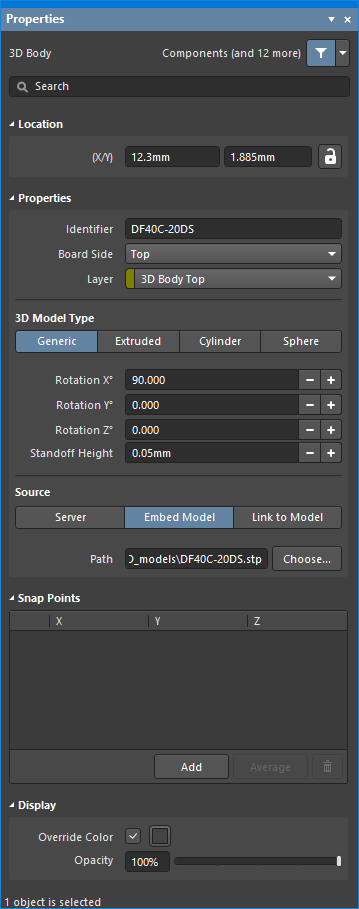
The 3D Body dialog (the first image) and the 3D Body mode of the Properties panel (the second image)
The 3D Body properties can be accessed prior to entering placement mode, from the PCB Editor – Defaults page of the Preferences dialog. This allows the default properties for the 3D Body object to be changed, which will be applied when placing subsequent 3D Bodies.
During placement, the 3D Body mode of the Properties panel can be accessed by pressing the Tab key. Once the 3D Body is placed, all options appear.
After placement, the 3D Body dialog can be accessed by:
- Double-clicking on the placed 3D Body object.
- Placing the cursor over the 3D Body object, right-clicking then choosing Properties from the context menu.
After placement, the 3D Body mode of the Properties panel can be accessed in one of the following ways:
- If the Properties panel is already active, select the 3D Body object.
- After selecting the 3D Body object, select the Properties panel from the Panels button at the bottom right of the design space or select View » Panels » Properties from the main menus.
If the
Double Click Runs Interactive Properties option is enabled (default) on the
PCB Editor – General page of the
Preferences dialog, when the primitive is double-clicked or you right-click on a selected primitive then choose
Properties, the
Properties panel will open. When the
Double Click Runs Interactive Properties option is disabled, the dialog will open.
Press Ctrl+Q to toggle the units of measurement currently used in the dialog/panel between metric (mm) and imperial (mil). This only affects the display of measurements in the dialog/panel; it does not change the measurement unit specified for the board, which is configured in the Units setting in the Properties panel when there are no objects selected in the design space.
Editing Multiple Objects
The Properties panel supports editing multiple objects, where the property settings that are identical in all currently selected objects may be modified. When multiples of the same object type are selected manually, via the Find Similar Objects dialog or through a Filter or List panel, a Properties panel field entry can be edited for all selected objects. If values of a property are different for objects in the selection, the appropriate field will be shown as an asterisk (*) – a new property value will be applied to all selected objects.
Editing via a List Panel
Panel pages: PCB List, PCB Filter, PCBLIB List, PCBLIB Filter
A List panel allows you to display design objects from one or more documents in tabular format, enabling quick inspection and modification of object attributes. Used in conjunction with appropriate filtering – by using the applicable Filter panel, or the Find Similar Objects dialog – it enables the display of just those objects falling under the scope of the active filter – allowing you to target and edit multiple design objects with greater accuracy and efficiency.
Note
There are a number of tools and techniques for working with 3D Body objects and working in the 3D Layout mode. Refer to The 3D Advantage in ECAD-MCAD Integration page to learn more.
Working with an Extruded, Spherical, or Cylindrical 3D Body Object
Alongside generic 3D Body objects, the following 3D objects can be used:
Refer to the collapsible sections below to learn more about different aspects of working with these 3D Body objects.
Placing an Extruded, Spherical, or Cylindrical 3D Body ObjectExpandСвернуть
Availability
Extruded, spherical, and cylindrical 3D Body objects are available for placement in both the PCB and PCB Library Editors by:
- Choosing the Place » Extruded 3D Body command from the main menus.
- Locating and using the Extruded 3D Body command () on the Active Bar.
For a grouped set of Active Bar commands (indicated by a triangle at the bottom-right corner of the button), the button displays the last-used command. Click and hold on the active button to access a menu of all associated commands for that grouping.
Placement
In some situations, it is easier to place a 3D Body in 2D Layout Mode, in other situations it is easier to place one in 3D Layout Mode. At any time, the 2 and 3 shortcut keys can be used to switch back and forth between the two layout modes.
If you switch to 3D mode and the 3D Bodies are not visible, this indicates that the Show 3D Bodies option is disabled. Press Shift+Z at any time to toggle the display of 3D Bodies on or off. Alternatively, the option can be controlled in the View Options tab of the View Configuration panel.
It also is possible to control the display of each model-kind using an advanced setting on the System – General page of the Preferences dialog. Click the Advanced button; in the Advanced Settings dialog that opens, use the Legacy.PCB.3DModelsShowMode preference to control the display of model types: Value – 0 (both), 1 (Generic only), 2 (Extruded only).
To place an extruded, spherical, or cylindrical 3D Body object:
- After launching the command, the cursor will change to a crosshair and you will be in the default placement mode, placing an Extruded 3D Body object.
- Press Tab to pause placement and display the Properties panel in 3D Body mode. The pause button overlay ( ) will appear in the design space, indicating that you can access the fields of the Properties panel.
- In the Properties panel, enter a name for the 3D Body in the Identifier field. This is optional; the Identifier can help when there are multiple 3D Bodies being placed and also can be used to target this 3D Body in a design rule if required.
- Select the required Board Side; typically this is set to
Top. In the PCB library editor, the footprint is built for the top side of the board; it can be flipped to the bottom during the PCB design process if required.
- Select the mechanical Layer on which the 3D Body is to be placed. Component-type mechanical layers should be paired with a second mechanical layer so that if the component is flipped from the top side of the board to the bottom side, its mechanical detail, such as the 3D Body, will move to the paired mechanical layer. Mechanical layers are paired in the Layers and Colors tab of the View Configuration panel. Refer to the panel page for more information.
- Select the 3D Model Type from the available shapes: Extruded, Cylinder or Sphere.
- Each shape must have a defined size before it can be placed. If the chosen shape is:
- Extruded – then define the Overall Height.
- Cylinder – define the Height and Radius.
- Sphere – define the Radius.
- In the Display region of the panel, click the Color button to set the color and adjust the Opacity as required.
- Once editing is complete, click the pause button overlay to return to the design space.
- If the shape is a Cylinder or Sphere:
- The cursor will be moving in the design space with a rectangular shape attached; click to place the 3D Body.
- Right-click or press Esc to terminate 3D Body object placement.
- If the shape is Extruded, the cursor will present, ready to define the polygonal base shape of the extruded 3D Body:
- Click to define the first vertex.
- Move the cursor ready to place the second vertex. The default behavior is to place two edges with each click, with a user-defined corner shape between them. Refer to the Extruded 3D Body Placement Modes section below to learn more.
- Continue to move the mouse and click to place further vertices.
- After placing the final vertex, right-click or press Esc to close and complete placement of the 3D Body. There is no need to manually close the 3D Body as the software will automatically complete the shape by connecting the start point to the final point placed.
Extruded 3D Body Placement Modes
While placing an extruded 3D Body there are five available corner modes, four of which also have corner direction sub-modes. During placement:
- Press Shift+Spacebar to cycle through the five available corner modes.
- Press Spacebar to toggle between the two corner direction sub-modes.
- When in either of the arc corner modes, hold the
 or keys to shrink or grow the arc. Hold the Shift key as you press to accelerate arc resizing.
- Press the 1 shortcut key to toggle between placing
![]() two edges per click, or one edge per click. In the second mode, the dashed edge is referred to as the look-ahead segment.
two edges per click, or one edge per click. In the second mode, the dashed edge is referred to as the look-ahead segment.
- Press the Backspace key to remove the last vertex.
Press Shift+F1 during placement to display a list of available in-command shortcuts.

An extruded 3D Body object; note the reference point shown in the 2D and 3D views.
Editing an Extruded, Spherical, or Cylindrical 3D Body ObjectExpandСвернуть
Graphical Editing
This method of editing allows you to select a placed 3D body object directly in the design space and change its size, shape, or location graphically.
Note that sphere and cylinder 3D body types can only be moved in the design space. They cannot be modified graphically with respect to their size or shape.
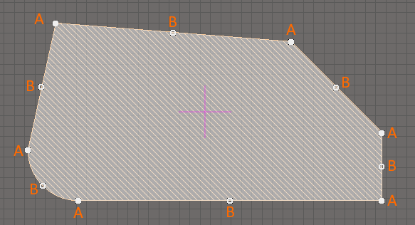
For an extruded 3D body, click once on the object to select it, which puts it into edit mode. The outer shape of the 3D body object is defined by a series of edges: where each edge is represented by an end vertex at each end, shown as a solid white square (A in the image below); and a center vertex in the middle, shown as a hollow white square (B in the image below). Each end vertex represents the location where two edges meet.
Standard polygonal shape editing techniques are available for editing the shape.
When editing a polygonal object, there are three editing modes available, Slide/Miter, Incurvate (arc) and Move. The current mode can be changed while dragging a vertex or an edge by pressing Shift+Spacebar to cycle through the 3 modes.
- Slide/Miter – click and hold on an edge or a center vertex to slide that edge; click and hold on an end vertex to miter the corner.
- Incurvate – click and hold on an edge or a center vertex to incurvate that edge; click and hold on an end vertex to incurvate (arc miter) the corner.
- Move – click and hold on an edge or a center vertex to break that edge into two edges; click and hold on an end vertex to freely move that corner.
Feedback about where the cursor is on the board and which editing mode is currently active can be viewed on the Status bar and in the Heads-Up display.
During editing, you can also:
- Ctrl+click and hold anywhere along an edge away from editing handles to insert a new vertex.
- To remove a vertex, click and hold on the vertex then press the Delete key.
- Click anywhere on the 3D body away from editing handles then drag to reposition it. While dragging, the 3D body can be rotated or mirrored:
- Press the Spacebar to rotate the 3D body counterclockwise or Shift+Spacebar for clockwise rotation. The Rotation Step size is defined on the PCB Editor – General page of the Preferences dialog.
- Press the X or Y keys to mirror the 3D body along the X-axis or Y-axis.
The Extruded and Cylinder 3D Body shapes cannot be rotated around all three axes. For example, an Extruded object can only be rotated around the Z-axis (looking down into the object), and a Cylindrical object can be rotated around the Y and Z axes.
If an object needs to be rotated around another axis, it can be converted to a STEP object. To convert a free 3D Body object, select it in the design space then right-click and choose the Convert To STEP command from the context menu. The command will not be available if there is no object selected, or if there is more than one object selected. Once an object has been converted to STEP, it can no longer be re-sized in the design space.

Convert an extruded shape to STEP if you need to rotate it around the X or Y axes.
If attempting to graphically modify an object that has its
Locked property enabled, a dialog will appear asking for confirmation to proceed with the edit. If the
Protect Locked Objects option is enabled on the
PCB Editor – General page of the
Preferences dialog and the
Locked option for that design object is enabled as well, then that object cannot be graphically edited. Double-click the locked object to select it then disable the
Locked property in the
Properties or
List panel or disable the
Protect Locked Objects option to graphically edit the object.
Non-Graphical Editing
The following methods of non-graphical editing are available.
Editing via the 3D Body Dialog or Properties Panel
Properties page: 3D Body Properties
This method of editing uses the associated 3D Body dialog and the Properties panel mode to modify the properties of a 3D Body object (while the options are the same in the dialog and the panel, the order and placement of the options may differ slightly).
 and the 3D Body mode of the Properties panel (the second image)")
The 3D Body dialog (the first image) and the 3D Body mode of the Properties panel (the second image)
The 3D Body properties can be accessed prior to entering placement mode, from the PCB Editor – Defaults page of the Preferences dialog. This allows the default properties for the 3D Body object to be changed, which will be applied when placing subsequent 3D Bodies.
During placement, the 3D Body mode of the Properties panel can be accessed by pressing the Tab key. Once the 3D Body is placed, all options appear.
After placement, the 3D Body dialog can be accessed by:
- Double-clicking on the placed 3D Body object.
- Placing the cursor over the 3D Body object, right-clicking then choosing Properties from the context menu.
After placement, the 3D Body mode of the Properties panel can be accessed in one of the following ways:
- If the Properties panel is already active, select the 3D Body object.
- After selecting the 3D Body object, select the Properties panel from the Panels button at the bottom right of the design space or select View » Panels » Properties from the main menus.
If the
Double Click Runs Interactive Properties option is enabled (default) on the
PCB Editor – General page of the
Preferences dialog, when the primitive is double-clicked or you right-click on a selected primitive then choose
Properties, the
Properties panel will open. When the
Double Click Runs Interactive Properties option is disabled, the dialog will open.
Press Ctrl+Q to toggle the units of measurement currently used in the dialog/panel between metric (mm) and imperial (mil). This only affects the display of measurements in the dialog/panel; it does not change the measurement unit specified for the board, which is configured in the Units setting in the Properties panel when there are no objects selected in the design space.
Editing Multiple Objects
The Properties panel supports editing multiple objects, where the property settings that are identical in all currently selected objects may be modified. When multiples of the same object type are selected manually, via the Find Similar Objects dialog or through a Filter or List panel, a Properties panel field entry can be edited for all selected objects. If values of a property are different for objects in the selection, the appropriate field will be shown as an asterisk (*) – a new property value will be applied to all selected objects.
Editing via a List Panel
Panel pages: PCB List, PCB Filter, PCBLIB List, PCBLIB Filter
A List panel allows you to display design objects from one or more documents in tabular format, enabling quick inspection and modification of object attributes. Used in conjunction with appropriate filtering – by using the applicable Filter panel, or the Find Similar Objects dialog – it enables the display of just those objects falling under the scope of the active filter – allowing you to target and edit multiple design objects with greater accuracy and efficiency.
