
Working with a 3D Body Object on a PCB in Altium Designer
Parent page: PCB Objects

Place 3D Bodies to represent the mounted physical component.
Summary
A 3D body is a primitive polygonal design object that is used to represent the three-dimensional shape of the physical component that is mounted on the assembled PCB. Any number of 3D body objects can be used together to create complex component shapes. You can place extruded polygon, cylindrical and spherical 3D Body shapes either in the PCB editor or into a PCB library component footprint.
As well as the simple 3D shapes that can be defined, a 3D Body object also can be used as a container into which you can import a standard-format generic 3D model, including STEP, SolidWorks and Parasolid format models.
The actual 3D shape is displayed when the editor is switched to 3D display mode (click View » 3D Layout Mode or press the 3 shortcut).
The following 3D objects can be used:
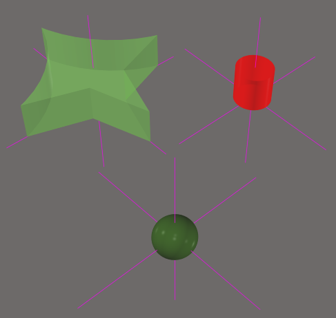
- Standard 3D Body Objects - place multiple instances of these to build up the required component shape, as shown in the animation above:
- Extruded
- Cylinder
- Sphere
- Generic models - 3D models are available from many component manufacturers and community websites. The following file formats are supported:
- STEP -
*.Stpand*.Step - SolidWorks parts -
*.SldPrt - Parasolid Models -
*.x_tand*.x_b
- STEP -
Availability
3D Body objects are available for placement in both the PCB and PCB Library Editors by:
- Choosing the Place » 3D Body command from the main menus.
- Locating and using the 3D Body command (
 ) on the Active Bar.
Placement - Standard 3D Body Object
To place a standard 3D Body object:
- Launch the Place » 3D Body command. The cursor will change to a crosshair and you will be in the default placement mode, placing an Extruded 3D Body object.
- Press Tab to pause placement and display the Properties panel in 3D Body mode. The workspace pause button overlay (
 ) will appear in the workspace, indicating that you can access the fields of the Properties panel.
 - In the Properties panel, enter a name for the 3D Body in the Identifier field. This is optional; the Identifier can help when there are multiple 3D Bodies being placed and also can be used to target this 3D Body in a design rule, if required.
- Select the required Board Side; typically this is set to
Top. In the PCB library editor the footprint is built for the top side of the board; it can be flipped to the bottom during the PCB design process, if required. - Select the mechanical Layer on which the 3D Body is to be placed. Component-type mechanical layers should be paired with a second mechanical layer so that if the component is flipped from the top side of the board to the bottom side, its mechanical detail, such as the 3D Body, will move to the paired mechanical layer. Mechanical layers are paired in the Layers and Colors tab of the View Configuration panel. Refer to the panel page for more information.
- Select the 3D Model Type from the available shapes: Extruded, Cylinder or Sphere. Alternatively, enable the Generic option if you want to embed an external 3D model. Click here to read more on this below.
- Each shape must have a defined size before it can be placed. If the chosen shape is:
- Extruded - then define the Overall Height.
- Cylinder - define the Height and Radius.
- Sphere - define the Radius.
- In the Display region of the panel, click the Color button to set the color and adjust the Opacity as required.
- Once editing is complete, click the workspace pause button overlay to return to the workspace.
- If the shape is a Cylinder or Sphere:
- The cursor will be moving in the workspace with a rectangular shape attached; click to place the 3D Body.
- Right-click or press Esc to terminate 3D Body object placement.
- If the shape is Extruded, the cursor will present, ready to define the the polygonal base shape of the extruded 3D Body:
- Click to define the first vertex.
- Move the cursor ready to place the second vertex. The default behavior is to place two edges with each click, with a user-defined corner shape between them. Refer to the Placement Modes section to learn more.
- Continue to move the mouse and click to place further vertices.
- After placing the final vertex, right-click or press Esc to close and complete placement of the 3D Body. There is no need to manually close the 3D Body as the software will automatically complete the shape by connecting the start point to the final point placed.
Extruded 3D Body Placement Modes
While placing an extruded 3D Body there are five available corner modes, four of which also have corner direction sub-modes. During placement:
- Press Shift+Spacebar to cycle through the five available corner modes: 45 degree, 45 degree with arc, 90 degree, 90 degree with arc, and Any Angle.
- Press Spacebar to toggle between the two corner direction sub-modes.
- When in either of the arc corner modes, hold the
 or keys to shrink or grow the arc. Hold the Shift key as you press to accelerate arc resizing.
 - Press the 1 shortcut key to toggle between placing 2 edges per click, or one edge per click. In the second mode, the dashed edge is referred to as the look-ahead segment.
- Press the Backspace key to remove the last vertex.
 45 degree
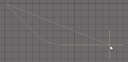 45 degree with arc
 90 degree
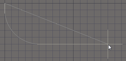 90 degree with arc
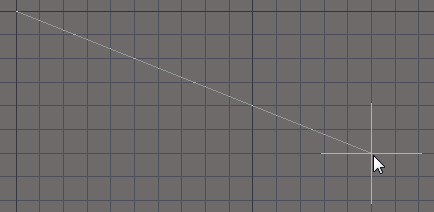 and Any Angle.
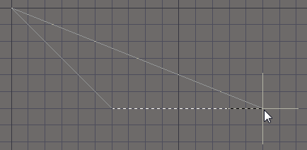 or one edge per click
  An extruded 3D Body object; note the reference point shown in the 2D and 3D views.
Rotating a Standard 3D Body
The standard Extruded and Cylinder 3D Body shapes cannot be rotated around all three axes. For example, an Extruded object can only be rotated around the Z axis (looking down into the object), and a Cylindrical object can be rotated around the Y and Z axes.
If an object needs to be rotated around another axis, it can be converted to a STEP object. To convert a free 3D Body object, select it in the workspace then right-click and choose the Convert To STEP command from the context menu. The command will not be available if there is no object selected, or if there is more than one object selected. Once an object has been converted to STEP, it can no longer be re-sized in the workspace.
 Convert an extruded shape to STEP if you need to rotate it around the X or Y axes.
Placement - Generic Model
A generic model, such as a STEP-format component model, is placed by linking or embedding it in a 3D Body object.
To place a generic model:
- Complete steps 1 to 4 as described in the Standard 3D Body Placement section.
- In the 3D Model Type region of the Properties panel, click the Generic button.
- In the Source section of the Properties panel, click to set the source to:
- Vault - the 3D model is to be retrieved from a managed content server, or
- Embed Model - the 3D model file is to be embedded inside the PCB library or PCB file, or
- Link to Model - the 3D model file is linked to the PCB, this option is not available in the PCB library editor.
- Click the Choose button to load the model file. The behavior is slightly different for each Source option:
- Vault - click the Choose button to open the Choose Item dialog, where you can access Items in a connected server. Refer to the Referencing a Server-based 3D Model Item section to learn more.
- Embed Model - the standard Windows Open dialog will open. Select the required file type from the drop-down then browse and locate the required model file.
- Link to Model - The Choose Model dialog will open. Select the required model then click OK. If the required model location is not listed in the Choose Model dialog, refer to the Working with a Linked Model section below to learn more.
- You will return to the Properties panel, with the path and filename of the model displayed in the Path field.
- The default model color can be overridden, if required. In the Display section of the panel, enable the Override Color checkbox then set the Color and the Opacity as required.
- Once editing in the panel is complete, click the workspace pause button overlay to return to the workspace.
- The model will be floating on the cursor; position it then click to place.
- It is quite likely that the generic model will need to be re-oriented; refer to the Techniques for Orienting a Generic Model section to learn more.
 Accurate and detailed component models are available.
Working with a Linked Model
Typically this feature is used to link to a large MCAD model, such as the product case, that you want to place in the PCB editor to check the loaded board for fit. The advantage of linking the model is that if the software detects that an external linked model file has been updated, it will warn on file-open, allowing the linked model to be refreshed.
Linked models must be stored in a location that is defined on the PCB Editor - Models page of the Preferences dialog. If the required location is not listed in the Choose Model dialog, click the Add Directories button to open the Preferences dialog.
To add a new location in the PCB Editor - Models Preferences page:
- Either type in the full path or click the button to the right of the Model Search Path field (
 )
to open the Windows Browse for Folder dialog.
)
to open the Windows Browse for Folder dialog. - After locating the required folder and clicking OK in the dialog, you will return to the Preferences dialog. Click the Add button to include this location in the list of available model search paths.
- Note that only the specified folder is searched for model files; sub-folders are not searched.
- Once the required location has been specified, click OK to close the Preferences dialog and return to the Choose Model dialog.
Referencing a Server-based 3D Model Item
To reference a 3D model that is stored in a server:
- Select Vault in the Source region of the 3D Body mode of the Properties panel.
- Click the Choose button to the right of the Item Revision field.
- The Choose Item dialog will open; use this dialog to browse to and select the revision of the required 3D Model Item.
- After clicking OK, a link will be created between the 3D Body and the target revision of the 3D Model Item. Information is shown in the Details region of the Properties panel.
Graphical Editing
This method of editing allows you to select a placed 3D body object directly in the workspace and change its size, shape, or location graphically.
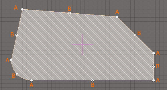
For an extruded 3D body, click once on the object to select it, which puts it into edit mode. The outer shape of the 3D body object is defined by a series of edges: where each edge is represented by an end vertex at each end, shown as a solid white square (A in the image below); and a center vertex in the middle, shown as a hollow white square (B in the image below). Each end vertex represents the location where two edges meet.
Standard polygonal shape editing techniques are available for editing the shape.
When editing a polygonal object, there are three editing modes available, Slide/Miter, Incurvate (arc) and Move. The current mode can be changed while dragging a vertex or an edge by pressing Shift+Spacebar to cycle through the 3 modes.
- Slide/Miter - click and hold on an edge or a center vertex to slide that edge; click and hold on an end vertex to miter the corner.
- Incurvate - click and hold on an edge or a center vertex to incurvate that edge; click and hold on an end vertex to incurvate (arc miter) the corner.
- Move - click and hold on an edge or a center vertex to break that edge into two edges; click and hold on an end vertex to freely move that corner.
During editing, you can also:
- Ctrl+click and hold anywhere along an edge away from editing handles to insert a new vertex.
- To remove a vertex, click and hold on the vertex then press the Delete key.
- Click anywhere on the 3D body away from editing handles then drag to reposition it. While dragging, the 3D body can be rotated or mirrored:
- Press the Spacebar to rotate the 3D body counterclockwise or Shift+Spacebar for clockwise rotation. The Rotation Step size is defined on the PCB Editor – General page of the Preferences dialog.
- Press the X or Y keys to mirror the 3D body along the X-axis or Y-axis.
Non-Graphical Editing
The following methods of non-graphical editing are available:
Editing Via the Properties Panel
Properties page: 3D Body Properties
The properties of a 3D Body object can be edited in the PCB editor's Properties panel, which allows editing of all item(s) currently selected in the workspace.

The 3D Body mode of the Properties panel
During placement, the panel can be accessed by pressing the Tab key.
To access the properties of a placed 3D Body:
- Double-click anywhere on the 3D Body object.
- Right-click on the 3D Body perimeter then select Properties from the context menu.
- If the Properties panel is already active, click anywhere on the 3D Body object to select it.
Editing Multiple objects
The Properties panel supports editing multiple objects, where the property settings that are identical in all currently selected objects may be modified. When multiples of the same object type are selected manually, via the Find Similar Objects dialog or through a Filter or List panel, a Properties panel field entry that is not shown as an asterisk (*) may be edited for all selected objects.
Editing Via the List Panel
Panel pages: PCB List, PCBLIB List
A PCB List panel allows you to display design objects from one or more documents in tabular format, enabling quick inspection and modification of object attributes. Used in conjunction with appropriate filtering, it enables the display of just those objects falling under the scope of the active filter – allowing you to target and edit multiple design objects with greater accuracy and efficiency.
Other 3D Body Features
There are a number of tools and techniques for working with 3D Body objects and working in the 3D Layout mode. Some of these are summarized below. Refer also to The Advantage of 3D in ECAD-MCAD Integration page to learn more.
Maintaining Component Clearances
Add Component Clearance design rules to check for collisions between components that include 3D body objects in the X, Y and Z planes. This allows you to the check the clearance of component over another component. Multiple rules can be defined to handle different clearance requirements. Note that the Design Rule Check does not test if a 3D body object is passing through the board.
Refer to the Component Clearance design rule to learn more.
Configuring the Mechanical and Display Layers
3D Body objects are normally placed on a mechanical layer. If the 3D Body object is to represent a component, the 3D Body object should be added to the component footprint in the PCB library editor.
Any mechanical layer can be used to place 3D Body objects. Typically a layer is chosen and named and that layer is used for 3D Body objects only. Because PCB components can be mounted on either surface of the finished PCB, the software supports the pairing of mechanical layers. Working in exactly the same way as the paired top and bottom silkscreen layers, when a component is flipped from the top side to the bottom side, any object on a mechanical layer that is paired is automatically flipped on to the paired mechanical layer.
Layer pairing is not required for rendering of the model in 3D; the software uses the Board Side property to determine which surface the object is on and in which direction to render the 3D Body. Layer pairs are important if you need to generate side-of-board assembly printouts that include components on one side of the board.
Reference Point and Snap Points
Reference and Snap Points provide a way of holding a 3D Body object during placement. If the Snap to Center option is enabled in the PCB Editor - General page of the Preferences dialog, the cursor will automatically snap to the nearest vertex / reference point / snap point when you click and hold to move the object.
The Reference Point
Each of the 3D Body types - Extruded, Cylindrical and Sphere - has a reference point or origin.
- For a cylinder and sphere, the reference is the center point of the object's circular shape on the X-Y plane.
- For an extruded object, the reference is set to the location X-length/2, Y-length/2 when viewed from above.
- It is the position of this reference point in the workspace that is shown in the X/Y Location in the Properties panel.

 Standard 3D Body objects have a reference point, as shown in the images. Note that the reference point lines are not long so they may not appear outside the object.
To display the reference point, enable the 3D Body Reference Point / Custom Snap Points option in the System Color section of the Layers & Colors tab of the View Configurations panel and set the color as required.
Defining Snap Points
Snap points are user-defined locations, which allow the object to be held at that location as it is moved in the workspace. Snap points are typically assigned to an edge or corner of the object or a center location, for example, the center of a pin or mounting peg.
Snap points can be added by entering the X, Y & Z locations in the Snap Points region of the Properties panel or they can be added interactively using the Add Snap Points From Vertices command. It is easier to interactively add Snap points in 3D mode.
To add snap points:
- Press 3 to switch to 3D layout mode.
- Select the Tools » 3D Body Placement » Add Snap Points From Vertices command.
- As shown on the Status bar, the next step is to Pick the STEP model to add snap points to; click to select the required standard 3D Body object or generic model.
- Press the Spacebar to select the required mode.
- Click a vertex to define the snap point location.
- If the two-click mode is being used, click a second vertex to define the second location; the snap point will be created midway between the two click locations as shown in the video below.
- Continue placing snap points or right-click or press Esc to terminate the command.
Video demonstrating the process of importing a generic model and defining three snap points on it.
Techniques for Orienting a Generic Model
It is common that a generic model designed in an MCAD tool will need to be re-oriented to use in board design. This can be achieved by:
- Using the commands in the Tools » 3D Body Placement sub-menu.
- Interactively editing its X, Y & Z properties in the Properties panel.
Using the Orientation Commands
The software includes commands for orienting and positioning a component. It requires the designer to select three snap points that lie on the surface of the PCB then indicate the three reference points on the PCB to which each of these snap points should be mated. The process is described and also demonstrated (in the video) below.
To position and align a model to a footprint:
- Switch to 3D Layout Mode (3 shortcut).
- Run the Tools » 3D Body Placement » Orient and Position 3D Body command.
- The Status bar will prompt to select a model; click the generic model you want to reposition.
- Three anchors must now be selected, one after the other. Ideally these will be an accurate reference, such as a pre-defined model reference point, or a snap point located at the center of a pin. The Status bar will indicate which anchor you are currently up to. Note that the Status bar displays a numerical reference value for the vertex or snap point that is currently under the cursor - user-define Snap Points have a low value, from 2 upward; keep an eye on this value to help identify the correct click location. Refer to the Defining Snap Points section to learn more about adding Snap Points.
- Once the three anchors have been chosen, the next step is to select, in the same order, the three locations on the footprint where these anchors are to sit. Use the Status bar to guide you as you select the three locations. Note that the cursor will be blue as you move it through the workspace, but will change to green if you are over the center of an object, such as a pad.
- As soon as the third anchor location has been clicked on, the model will change its orientation and position as the software attempts to mate these three locations. The command will then terminate.
This process is demonstrated in the video below.
Video demonstrating the process of re-orienting a Generic Model.
Orienting a Generic Model in the Properties Panel
An excellent approach to orienting a model is to use the 3D Body mode of the Properties panel. Because the values can be edited from the keyboard, it is easy to quickly test various X, Y or Z values and change the orientation as you observe the model in 3D. The video below demonstrates this, including the use of the keyboard to:
- Ctrl+F - to Flip the view over.
- M - to move an object.
- J - to Jump to a location in the workspace.
- R - to select Reference (the PCB library editor workspace origin) from the Jump sub-menu.
- Enter - to apply the value just typed into the panel and also to place the model being moved.
Video demonstrating the process of re-orienting a Generic Model.
Including a Texture on an Extruded 3D Body
Extruded objects also can include an image over-layed on the upper most surface. When a Texture File is added, it is automatically stretched to fit to cover the entire upper surface of the 3D body, as shown in the image below. This can be adjusted by altering the Center location, Size and Rotation settings in the 3D mode of the Properties panel. Note that the texture file is embedded in the Library or Board file.
Supported Texture File formats include: *.bmp;*.dds;*.dib;*.hdr;*.jpg;*.pfm;*.png;*.ppm; and *.tga.
 A texture or logo can be added to an extruded 3D Body object.