
Working with a Connection Object on a PCB in Altium Designer
Parent page: PCB Objects
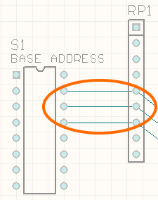
As-yet-unrouted connection lines between the
pads of two placed board components.
Summary
Connection lines are the visual representation of the logical connectivity between net objects. Each of these lines, connecting one pin in a net to another pin in the net, is called a From To. The entire set of connections (From Tos) for a design is often referred to as the 'ratsnest'.
The connection lines are subsequently used when interactively routing (or Autorouting) in order to achieve the physical, routed links, between the logically connected objects in each net.
Availability & Placement
Default connections (From Tos) are automatically generated and placed by the PCB's Connectivity Analyzer when nets are loaded into the PCB design document (i.e. when importing the design or design changes from the schematic). As such, a connection is not a design object that can be accessed and placed by the user.
Non-Graphical Editing
A connection object cannot be edited with respect to properties in the usual manner - it cannot be selected in the workspace, has no corresponding properties dialog, and cannot be edited graphically. The following sections take a look at what can be done with connection lines, through non-graphical editing.
Defining the Default Connection Line Color
The layer upon which connection lines are displayed can be enabled/disabled with respect to its visibility, using the corresponding Show checkbox for the Default Color for New Nets entry, in the System Colors region, on the Board Layers And Colors tab of the View Configurations dialog (Design » Board Layers & Colors, with the board in 2D Layout Mode).

The visibility and coloring for the connections (and from tos) can be controlled from the Board Layers And Colors tab of the View Configurations dialog
(provided the board is being viewed in 2D).
Define the display color by clicking on the color swatch to bring up a variant of the 2D System Colors dialog (which only allows changing the color for Connections and From Tos), from where you can choose from a range of predefined colors, or create your own custom color. You can save any view configurations for use in other projects.
Changing the Connection Line Color
An easy way to make important nets stand out during the routing process is to change the color of their connection lines. To do this, double-click the net name in the PCB panel (set to Nets mode) to access the Edit Net dialog, from where you can edit the connection line color.

Double-click in the PCB panel to edit a net's connection line color.
Displaying Connection Lines using Layer Colors
As well as setting the connection line color for individual nets, you can also display the connection lines using the colors of the start and end layers that the connection line travels between. These connection lines are displayed as dashed lines, using the colors of both the start and end layers. This feature is ideal when you are routing a multi-layer board, as you can easily tell the target layer that the connection being routed must get to.
To use the color-by-layer feature, enable the Use Layer Colors for Connection Drawing option, on the View Options tab of the View Configurations dialog. The images below show the same region of the board in single layer mode, firstly from the Top Layer, then from the Bottom Layer.

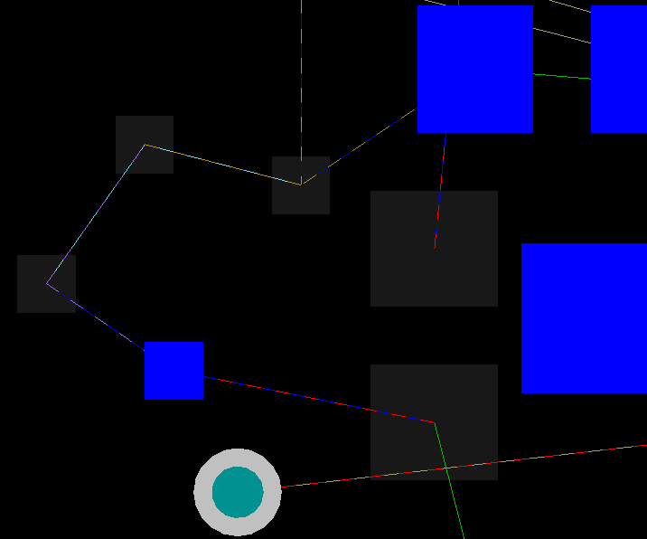
An example of connection lines that connect between different layers in a multi-layer board, in single layer mode.
Displaying Connection Lines in Single Layer Mode
A multi-layer board is visually dense, making it difficult to interpret what is going on. To help with this, you can easily switch the layer display from the chosen Layers to Single Layer mode, by pressing the Shift+S shortcut. Normally, when you do, all connection lines that do not either start or end on the current layer are also hidden, as it is assumed that they are not relevant. To always display the connection lines, enable the Show All Connections in Single Layer Mode option, on the View Options tab of the View Configurations dialog.
Controlling Connection Line Visibility
You can control which connection lines in the entire ratsnest of connections are shown and which are hidden. Use the available commands on the View » Connections sub-menu to:
- Show or hide all connection lines for the design.
- Show or hide all connection lines associated with a chosen net.
- Show or hide the connection lines for all nets associated with a chosen component.
How From-To Objects Show in the Workspace
A system-generated From To does not appear in the workspace as a separate entity - only the associated pin-to-pin connection line for the From To is displayed, which is used for interactive routing/Autorouting guidance. A user-defined From To appears in the workspace as a dotted line, separate and distinct from the pin-to-pin connection line that is also displayed when the From To is added. The user-defined From To line controls where the associated pin-to-pin connection line starts and finishes.
If you specify user-defined From Tos for only part of a net, the PCB Editor will set the remaining pin-to-pin connections (system-generated From Tos) to the Shortest topology.
The type of From To determines how the Connectivity Analyzer treats the pin-to-pin connection line when, for example, a net object is moved or part of a net is manually routed:
- System-generated From To - the connection line can be moved as required as part of the Connectivity Analyzer's re-optimization to keep the default topology of the net (i.e. Shortest)
- User-defined From To - if the From To is not the result of selecting a predefined topology, the connection line is not considered as part of the Connectivity Analyzer's re-optimization process. If the From To is part of a predefined net topology (other than Shortest), the Connectivity Analyzer can include it in re-optimization, so long as the chosen topology is kept.
Connectivity During Interactive Routing
The PCB Editor is a connectivity-aware design environment. At all stages of routing your design, the software monitors and manages the netlist connectivity. Because the PCB's Connectivity Analyzer automatically monitors the completion status of the net you are routing, you can route without regard to the arrangement of the pin-to-pin connections. Once you complete a connection, the entire net is reanalyzed and connection lines are added and re-optimized as necessary.
There are two distinct advantages to this methodology. The first is that you can route a track to any primitive on the net, you do not have to route between the two points connected by the connection lines. The Connectivity Analyzer monitors your progress and adds and removes the connection lines automatically. The second is that the net connectivity is "unbreakable", you cannot accidentally break it into two unconnected parts. If you delete a track segment, the software detects the break and immediately adds a connection line to restore the net connectivity.
When a net is analyzed and a connection line added, the software automatically adds it based on the topology of the net. By default, all nets have their topology set to Shortest. For these nets, a from-to is added where the two sub-nets are closest. If the net has a user-defined topology applied, the connection line is added to maintain the topology and is shown as a dotted line (called a Broken Net Marker), indicating that the net should be routed between these two points to maintain the topology.
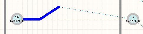
Example Broken Net Marker (top) - a system-generated from-to (connection line) advising how the
two points should be routed to satisfy topology.