
Configuring PCB 3D Body Object Properties in Altium Designer
Parent page: 3D Body
PCB Editor object properties are definable options that specify the visual style, content and behavior of the placed object. The property settings for each type of object are defined in two different ways:
- Pre-placement settings – most 3D Body object properties, or those that can logically be pre-defined, are available as editable default settings on the PCB Editor - Defaults page of the Preferences dialog (accessed from the
 button at the top-right of the workspace). Select Component Body in the Primitive List to reveal its options on the right.
- Post-placement settings – all 3D Body object properties are available for editing in the Properties panel when a placed 3D/Component Body is selected in the workspace.

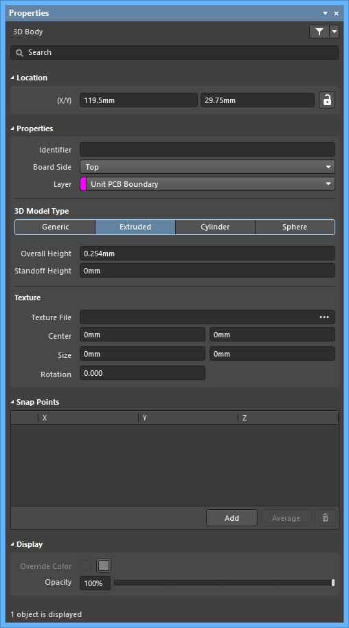 The Component Body default settings in the Preferences dialog and the 3D Body mode of the Properties panel
A 3D body is a primitive polygonal design object that is used to represent the 3-dimensional shape of the physical component that is mounted on the assembled PCB. Any number of 3D body objects can be used together to create complex shapes. The following 3D model formats can be used in Altium Designer:
- Altium Designer 3D Body Objects; place these to build up the required component shape.
- STEP models -
*.Stpand*.Step. - SolidWorks parts -
*.SldPrt. - Parasolid Models -
*.x_tand*.x_b.
Location (Properties panel only)
- (X/Y)
- X (first field) - the current X (horizontal) coordinate of the reference point of the 3D Body, relative to the current workspace origin. Edit to change the X position of the 3D Body. The value can be entered in either metric or imperial, include the units when entering a value whose units are not the current default.
- Y (second field) - The current Y (vertical) coordinate of the reference point of the 3D Body, relative to the current origin. Edit to change the Y position of the 3D Body. The value can be entered in either metric or imperial, include the units when entering a value whose units are not the current default.
Properties
- Identifier - enter a human-readable name used to identify the 3D Body object. Identifiers are useful for selecting a 3D body in the PCB panel.
- Board Side - use the drop-down to select from which side of the board the 3D Body will project. This setting is automatically changed if the 3D Body object is flipped to the other side of the board as part of a component flip.
- Layer - use the drop-down to select on which layer the 3D Body exists. Only layers that are currently enabled are available. If the chosen layer is paired, then when the body is flipped to the other side of the board as part of its component, it will also be moved to the paired layer.
3D Model Type
Select a model type for the 3D body object from the available options: Generic, Extruded, Cylinder, or Sphere. The options vary for each type and provide controls necessary for sizing and positioning in the 3D workspace.
- Generic - when this option is chosen, the 3D Body object simply acts as a container for it and it is automatically resized to enclose the chosen model.
- Rotation X° - the angular rotation (in degrees) of the 3D model around the X-axis.
- Rotation Y° - the angular rotation (in degrees) of the 3D model around the Y-axis.
- Rotation Z° - the angular rotation (in degrees) of the 3D model around the Z-axis.
- Standoff Height - the distance from the board surface to the underside of the 3D model. Use a negative value for a model that must pass down through the PCB.
- Source
- Vault
- Item Revision - the revision of the required 3D Model Item. Click the Choose button to the right of the Item Revision field to open the Choose Item dialog. Use this dialog to browse to and select the desired revision. After clicking OK, a link will be created between the 3D Body and the target revision of the 3D Model item.
- Vault - displays the target server. Use the Show in Explorer button to open the Explorer panel.
- Details - displays the revision details.
- Revision State - displays the status of the linked 3D Model item.
- Update - if a newer revision of the linked Item is available, click to use the latest revision.
- Embed Model - use to select a 3D model (STEP, Parasolid, SolidWorks Part) to embed.
- Path - click Choose to search for and select the path of the model.
- Link to Model - use to link to a 3D Model.
- Path - click Choose to search for and select the path of the model. Click
 to refresh the path.
- Path - click Choose to search for and select the path of the model. Click
- Vault
- Extruded
- Overall Height - the distance from the board surface to the topside of the extruded body.
- Standoff Height - the distance from the board surface to the underside of the extruded body. Use a negative value for extruded bodies that must pass down through the PCB.
- Texture
- Texture File - defines an image to by displayed on the top surface of the extruded body. Accepted file formats are
*.bmp,*.dds,*.dib,*.hdr,*.jpg,*.pfm,*.png,*.ppm,and *.tga. Click to open a dialog to search for and select the desired file.
 - Center - the X and Y offsets that the center of the texture image will have with respect to the center of the top surface of the extruded body. For example, a value of 100mil, 0mil will shift the center point of the image 100mils in the X direction from the center point of the top surface of the extruded body.
- Size - the width (X-direction) and height (Y-direction) of the texture image. By default, the texture image will be uniformly scaled to fit the bounds of the top surface of the extruded body.
- Rotation - the rotation of the extruded body.
- Texture File - defines an image to by displayed on the top surface of the extruded body. Accepted file formats are
- Cylinder
- Height - the height of the cylindrical body.
- Radius - the radius of the cylindrical body.
- Rotation X° - the angular rotation (in degrees) of the cylindrical body around the X-axis.
- Rotation Y° - the angular rotation (in degrees) of the cylindrical body around the Y-axis.
- Rotation Z° - the angular rotation (in degrees) of the cylindrical body around the Z-axis.
- Standoff Height - the distance from the board surface to the underside of the cylindrical body. Use a negative value for a cylindrical body that must pass down through the PCB.
- Sphere
- Radius - the radius of the spherical body.
- Standoff Height - the distance from the board surface to the lowest edge of the spherical body. Use a negative value for spherical body that must pass down through the PCB.
Snap Points
- Grid region - displays the X, Y, and Z snap points for the sphere.
- Add - click to add a new snap point.
- Average - click to use the averages of all selected snap points for one individual snap point. This option is available only when two or more snap points are selected in the grid.
-
 - click to delete the selected snap point.
Display
- Override Color - enable if desired, then click the color box to access options to specify the object's color.
- Opacity - use the slider bar or enter the percentage directly to specify the transparency of the 3D body from invisible (left-most) to completely opaque (right-most).