
Working with a Parameter Set Object on a Schematic Sheet in Altium Designer
This document is no longer available beyond version 21. Information can now be found here: Parameter Set for version 24
Parent page: Schematic Design Objects

A Parameter Set
Summary
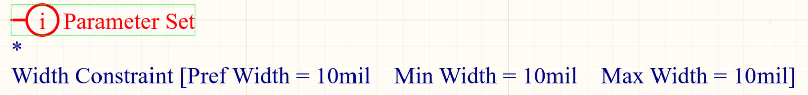
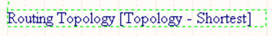
A parameter set is a design directive that allows design specifications to be associated with a net-type object within a schematic design. For example, use a parameter set to declare two nets to be members of a differential pair. It is the presence of specifically named parameters in the parameter set that the software uses to determine which design directive you are placing.
Availability
Parameter sets are available for placement in the schematic editor only. Both default (empty) and pre-defined (Differential Pair) parameter set directives are available. The only difference between an empty parameter set and a pre-defined parameter set is that the pre-defined parameter sets include a parameter, as described below.
Access the corresponding commands from the main Place menu as follows:
| • | Place » Directives » Parameter Set | 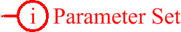 |
| • | Place » Directives » Differential Pair |  |
Placement
A parameter set can be used to attach parameters to a:
- Wire
- Bus
- Signal harness
- Sheet Symbol
After launching the command, the cursor will change to a cross-hair and you will enter design directive placement mode. Placement is made by performing the following actions:
- Position the cursor over a wire or other net object and click or press Enter to place.
- Continue placing further directives or right-click or press Esc to exit placement mode.
Additional actions that can be performed during placement – while the parameter set is still floating on the cursor are:
- Press the Tab key to pause the placement and access the Parameter Set mode of the Properties panel, from where its properties can be changed on the fly. Click the design space pause button overlay (
 ) to resume placement.
 - Press the Alt key to constrain the direction of movement to the horizontal or vertical axis, depending on the initial direction of movement.
- Press the Spacebar to rotate the arc counterclockwise or Shift+Spacebar for clockwise rotation. The action can also be performed while dragging the object. Rotation is in increments of 90°.
- Press the X or Y keys while in placement mode to flip the parameter set along the X-axis or Y-axis.
Graphical Editing
This method of editing allows you to select a placed parameter set directive directly in the design space and change its location or orientation graphically.
When a parameter set directive is selected in the design space, a dashed box will appear around the directive. The box encloses the area occupied by the directive only. For each visibility-enabled member parameter of the set, a dashed line will be visible, connecting the text field of the parameter to the body of the directive, which affirms association:
Click anywhere inside the dashed box then drag to reposition the parameter set as required. While dragging, the parameter set can be rotated (Spacebar/Shift+Spacebar) or mirrored (X or Y keys to mirror along the X-axis or Y-axis).
The parameter set's text fields (which can be graphically edited independently of the parent directive) can only be adjusted with respect to size by changing the Style option on the Schematic – Defaults page of the Preferences dialog. As such, editing handles are not available when any of these objects are selected.
Click anywhere inside the dashed box then drag to reposition the text object as required. While dragging, the text object can be rotated (Spacebar/Shift+Spacebar) or mirrored (X or Y keys to mirror along the X-axis or Y-axis).
If the Enable In-Place Editing option is enabled on the Schematic – General page of the Preferences dialog. You will be able to edit the value for a parameter directly in the design space (with the exception of parameters that have been added as rules). Select the text object and then click once to invoke the feature. Type the new value as required and then click away from the text object or press Enter to effect the change.
Non-Graphical Editing
The following methods of non-graphical editing are available.
Editing via the Parameter Set Dialog or Properties Panel
Panel page: Parameter Set Properties
This method of editing uses the associated Parameter Set dialog and the Properties panel mode to modify the properties of a parameter set object.

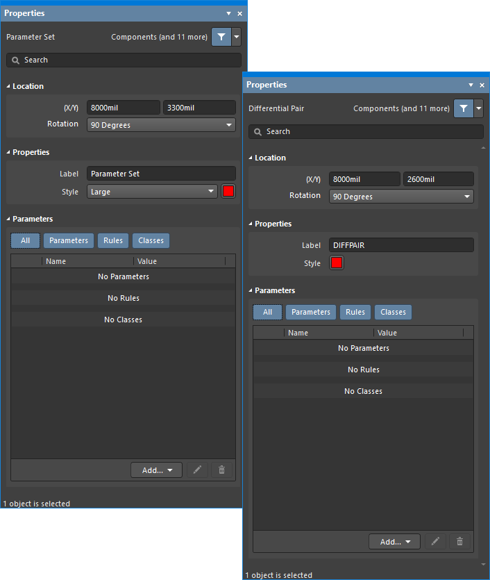
The Parameter Set dialog on the first image, and the Parameter Set mode of the Properties panel on the second image
After placement, the Parameter Set dialog can be accessed by:
- Double-clicking on the placed parameter set object.
- Placing the cursor over the parameter set object, right-clicking then choosing Properties from the context menu.
During placement, the Parameter Set mode of the Properties panel can be accessed by pressing the Tab key. Once the parameter set is placed, all options appear.
After placement, the Parameter Set mode of the Properties panel can be accessed in one of the following ways:
- If the Properties panel is already active, by selecting the parameter set object.
- After selecting the parameter set object, select the Properties panel from the Panels button at the bottom right of the design space or select View » Panels » Properties from the main menu.
Editing Multiple Objects
The Properties panel supports multiple object editing, where the property settings that are identical in all currently selected objects may be modified. When multiples of the same object type are selected manually, via the Find Similar Objects dialog or through a Filter or List panel, a Properties panel field entry that is not shown as an asterisk (*) can be edited for all selected objects.
Editing via a List Panel
Panel pages: SCH List, SCH Filter
A List panel allows you to display design objects from one or more documents in tabular format, enabling quick inspection and modification of object attributes. Used in conjunction with appropriate filtering – by using the applicable Filter panel or the Find Similar Objects dialog – it enables the display of just those objects falling under the scope of the active filter – allowing you to target and edit multiple design objects with greater accuracy and efficiency.
Example Usage
Multiple parameters can be added to the same parameter set object. In the image below, the Differential Pair directive was placed to touch the edge of the blanket. It was then edited to include a Net Class Name parameter and a Rule parameter. When the design is synchronized with the PCB, these additional elements will be created:
- Eight PCB differential pairs
- A PCB net class called
ROCKET_IO_LINES, containing the 16 named nets that are under the blanket - A Differential Pair Routing design rule, with a scope of
InNetClass('ROCKET_IO_LINES')

By using a blanket, only one Differential Pair directive is required. As well as defining the differential pairs, it also specifies a Net Class and a Differential Pair Routing rule. These nets will become members of that Net Class, and that Net Class will be used to scope the Differential Pair Routing rule.
Notes
- When placing a default parameter set directive, there will be no existing parameters.
- A Parameter Set directive allows you to assign PCB layout information to a net in the schematic. When a PCB is created from the schematic, the information in the Parameter Set is used to create relevant PCB design rules. The information specified by a Parameter Set directive is applied only to the net(s) to which it is connected.
- Net Class directives enable you to create user-defined net classes on the schematic. When a PCB is created from the schematic, the information in a Net Class directive is used to create the corresponding Net Class on the PCB. To make a net a member of a net class, attach a parameter set directive to the relevant wire or bus and a class whose name is set to the desired class. The Generate Net Classes option (for User-Defined Classes) must be enabled on the Class Generation tab of the Project Options dialog to use this feature.
- If a Net Class directive has been defined for a net, then any PCB design rules that are also created by that parameter set object will have a rule scope of Net Class, when the design is transferred to the PCB editor.
- A Net Class directive can be created from your placed Parameter Set directive by adding a class that must have its value set to the required PCB Net Class.
- A Differential Pair directive allows you to define a differential pair object on the schematic. Attach a directive of this type to both the positive and negative nets of the intended pair or cover the pair with a blanket object to target multiple nets with a single directive. The nets themselves must be named with the suffixes of _P and _N. Each pair of directives (one for the positive net and one for the negative net) of this type will yield a differential pair object when transferred to the PCB during the synchronization process. Each of these differential pair objects will be added to the default Differential Pair class of All Differential Pairs. The name of a generated differential pair object will be the root name for the net pair on the schematic. For example, directives added to
RX0_NandRX0_Pon the schematic will generate a differential pair object on the PCB with the nameRX0. You can rename differential pair objects on the PCB side only.